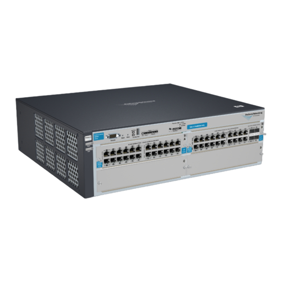
HP 4202vl-48GS Installation Manual - Page 9
Browse online or download pdf Installation Manual for Switch HP 4202vl-48GS. HP 4202vl-48GS 13 pages.

9/18/2020
The mounting brackets supplied with the switch allow user to mount it on awall. The illustrations below show mounting a 4208vl
Switch. All other 4200vl Switches would be mounted in a similar way.
CAUTION: For safe operation, do not install the switch with the vents or fans facing downward. The only recommended and
supported wall mounting orientationis with the unit upright and the modules facing out, as shown in the illustrations below.
Additionally, the switch should be mounted only to a wall or wood surface that is at least 1/2 in plywood or its equivalent.
1. Use a #1 Phillips (Cross-head) screw driver andattach the mounting bracketsto the switch with the included10 mm M4 screws.
Figure 11: Attaching brackets to the rear of the switch
Item Number
1
2. Attach the switch to the wall or wood surface with four 5/8 in number12 wood screwsor larger (Not included).
Figure 12: Mounting to a wall
Item Number
1
top
top
Connect the switch to a power source
1. Plug the included power cord into the switch's power connector and intoa nearby properly grounded AC power source.
If user have installed a redundant power supply module into the switch, it should be connected to a separate AC power source.
Then, if there is apower outage from one of the AC sources, the switch will continue tooperate by power coming from the other
source.
See the ProCurve Switch gl/xl/vl RPS Installation Guide for additional information.
2. Re-check the LEDs during self test.
top
HPE 4200 vl Switch Series - Installation
Description
10 mm M4 screws
Description
5/8 in number 12 wood screws
9/12
