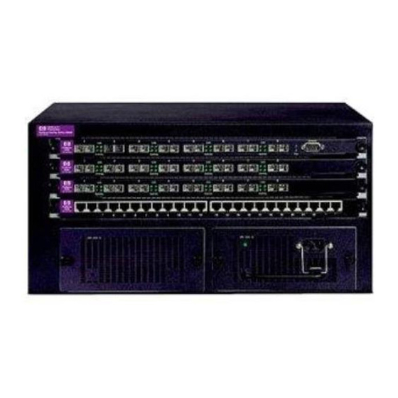
HP ProCurve Routing Switch 9308M / 9304M Reviewer's Guide
For 100 Mbps environments, the crosspoint matrix backplane can handle the traffic at full wire speed.
In this situation the traffic is limited by the total throughput of the 100 Mbps ports.
3.2 Congestion Control
Congestion occurs any time more packets are destined for a particular segment than that segment can
handle. All switches handle momentary congestion passively through buffering excess packets in
memory. The HP ProCurve Routing Switch 9304M and HP ProCurve Routing Switch 9308M handle the
congestion issue largely through running at full media speed. The only congestion the routing switches
need handle are packets destined for output ports that are congested due to external network segment
congestion. For this momentary situation, shared memory on the modules is used. Each module has
between 2 and 8 MB of shared memory, depending on the port type of the module.
Another standardized method to control congestion in a multiple network box environment is with the
802.3x Flow Control standard. The HP ProCurve routing switches support the 802.3x standard. Orderly
control of segment traffic occurs because a port on the routing switch can signal its congestion to the
segment, holding off segment traffic. For 802.3u to work correctly, the node(s) connected directly to
routing switch ports with flow control enabled also have to support the flow control protocol. Flow
control in the routing switches would only have to be used if the network segments external to the
routing switches were congested.
In the past, some switches have implemented a non-standard form of congestion control called
backpressure. The 802.3x Flow Control standard produces the same result as backpressure, but does it
in a standardized way. HP switches do not implement backpressure.
3.2.1 Head-of-line-blocking
A particular type of congestion that can be seen in some network devices is head-of-line-blocking
(HOLB). If a device exhibits HOLB, congestion on one outgoing port can affect the throughput of
another outgoing port that is not congested. Whether a device exhibits HOLB or not is dependent on
the inbound and outbound port buffer memory handling design. The shared memory architecture with
fair-weighted queues on the HP ProCurve routing switches does not allow HOLB to occur.
3.2.2 Bi-directional Congestion Testing (X-Stream)
Another congestion test currently being used is the bi-directional, multi-stream spray test. In this test
bursts of packet streams are sent into all tested ports at the same time. Collisions and congestion result
simultaneously on all ports. Throughput and packet loss rate (PLR) are recorded for each port.
While this is an ardent stress test, the HP ProCurve routing switches handle it with little problem
because of the wire-speed handling capability of the 9300 routing switches. Since X-Stream sends
packets to all other ports except the port the packet came in on, not all packets travel the backplane.
3.3 Latency
Latency is the amount of time the switch takes to process a packet. In store-and-forward devices, such
as with the HP ProCurve Routing Switch 9308M and 9304M, latency is reported by vendors on a LIFO
basis (last bit in, first bit out), i.e. the time elapsed between the end of the last bit of the packet going
into the switch to the beginning of the first bit of that packet emerging from the switch. Cut-through
switch latency is measured on a FIFO basis (first in, first out), time measured from the beginning of the
first bit of the packet going in to the switch to the beginning of the first bit of the outbound packet
coming out of the switch. Latency figures should be used with care when comparing store-and-forward
devices versus cut-through devices.
To add to the confusion, many testing houses report store-and-forward latency as FIFO because the
test equipment reports it that way. Following the actual definition of latency (RFC1242), which is the
time taken by the device to decide where to send a particular packet, store-and-forward routing switch
©1999 Hewlett-Packard Company
Revision 4.0 – 4/1/1999
27
Page: 22 of

