Aquatech Pressmain MG-LT Instructions Manual - Page 8
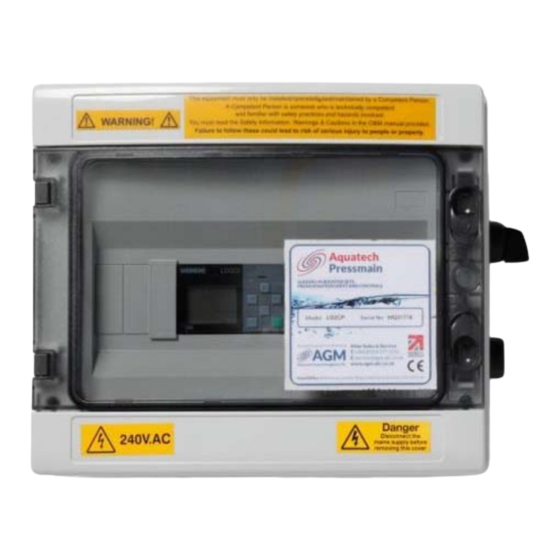
Browse online or download pdf Instructions Manual for Control Unit Aquatech Pressmain MG-LT. Aquatech Pressmain MG-LT 20 pages. Tankmatic tank level/temperature monitoring/control unit with smart relay control

1.1
GENERAL
These instructions are intended for the installer of this Level/Temperature Monitoring or control unit. Please
follow them carefully. Failure to install the equipment as recommended could invalidate the warranty provided
by AquaTech‐Pressmain to the buyer.
1.2
ADDITIONAL WARNINGS AND CAUTIONS
1.2.1
READ GENERAL SAFETY INFORMATION 0.0, WARNINGS 0.1 and CAUTIONS 0.2, 0.3 & 0.4
1.2.2
Installation of this equipment assumes prior correct and safe installation of the tank(s) and that you
are aware of all safety practices and hazards involved with the tank(s).
1.2.3
When installing sensors if you are unsure of any aspect you must seek the advice of the tank
manufacturer before commencing any modifications/alterations to the tank in order not to
compromise its performance.
1.2.4
Level sensors must not be subjected to more than 1.5 times the rating of the sensor; otherwise
irreversible damage may be done.
1.2.5
Temperature sensors must remain submerged at all times.
1.2.6
When chlorination of a tank is carried out, ensure that any residual chlorine is removed by thorough
flushing as detailed in the HSE approved code of practice L8, to avoid damaging the submersible
sensors. The normal level of chlorination is up to 2 parts per million (ppm), but shock dosing for
sterilization purposes, at 25‐50 ppm for 24‐48 hours is acceptable as long as all chlorine is removed
once the process is complete.
1.3
PROCEDURE
1.3.1 SENSORS
Sensors are available in standard form for attaching externally to the side of the tank, or submersible
form for suspending in the tank contents.
1.3.1.1 Standard Sensors ‐ externally mounted
Standard Level Sensor for monitoring liquid level:
A standard Level Sensor is fitted to the side of the tank via an isolating valve and 1/4" BSP parallel
female connection and wired to wall mounted connection box, or direct to the monitoring unit, within
5m (see Fig 1a.).
The depth of water displayed is that measured from the lowest point of the Level sensor.
Position the sensor at the minimum liquid level.
Standard Temperature Sensor:
A standard Temperature Sensor is fitted to the side of the tank in a 1/2" BSP parallel fitting, or
optionally into a sealed pocket (see Fig 1a.) and wired to wall mounted connection box or direct to the
monitoring unit, within 5m (see Fig 1a.). Position the Temperature sensor so that it is submerged at all
times.
1.3.1.2 Submersible Sensors
Submersible sensors are suspended in the liquid from a connection box on top of the tank as shown in
Fig 1b. They are restrained by a weighted guide wire or by a stilling tube to avoid turbulence damaging
the sensor.
Drilling the tank lid to take the flange (where supplied) see Fig 2
Select a suitable area of the tank, away from turbulence, for the sensors to be fitted.
Cut 80mm diameter hole taking care to prevent any swarf falling into the tank. Equally spaced about
this hole, mark 4 holes as shown in Fig 2, drill and tap M5 or fit clench nuts if required.
Aquatech‐Pressmain Instruction manual\Tankmatic smart relay MG‐LT
1. INSTALLATION INSTRUCTIONS
Tankmatic Smart Relay
8
