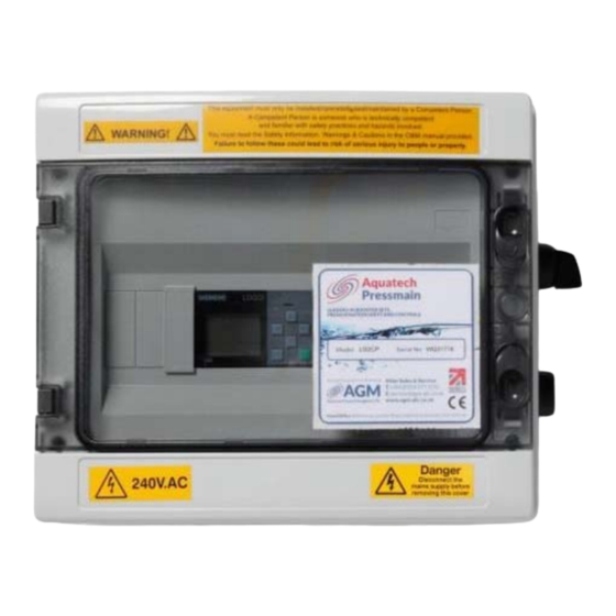
Aquatech Pressmain MG-T Instructions Manual - Page 5
Browse online or download pdf Instructions Manual for Control Unit Aquatech Pressmain MG-T. Aquatech Pressmain MG-T 20 pages. Tankmatic tank level/temperature monitoring/control unit with smart relay control

0.2.9
Ensure the electrical supply is the correct voltage, current, frequency and type for the equipment
supplied and that suitable circuit protection equipment is installed in the supply. Incorrect electrical
installation could be an electric shock/burns/fire hazard.
0.2.10
When accessing the control panel to make electrical connections adopt anti‐static procedures e.g.
wear anti‐static earthed wristband, to avoid risk of damaging the controller.
0.2.11
All products that are packaged to include Pressure vessel(s)/Hydraulic Accumulator(s)/Expansion
Vessel(s) are classed as "Assemblies" under the Pressure Equipment Directive (PED). Where units are
despatched with "Loose" vessel(s) for assembly on site it is absolutely essential that they be installed
as detailed in the instructions using the fittings provided where appropriate. Failure to observe this
will nullify compliance with the PED and may present a safety hazard. Your warranty may also be
affected.
0.2.12
Where Hydraulic Accumulator(s)/Expansion Vessel(s) are supplied as a loose item, they must be
installed/connected correctly before operating the equipment, otherwise serious damage from over‐
pressure/pump overheating could occur.
0.2.13
Do not operate this equipment/pumpset prior to commissioning (section 2.2) This could cause
irreparable damage to sensors/equipment/pumpset/pipework/system components.
0.2.14
Isolate the sensors/equipment/pumpset before pressure testing system. Excess pressure could
irreparably damage the pressure transducer, pressure switches (where fitted) and the diaphragms of
pressure vessel/hydraulic accumulators.
0.2.15
Where applicable it is the installers' responsibility to ensure subsequent pipework etc can accept the
pressures generated by the equipment/pumpset and to install an overpressure safety device into the
system with due respect to the suction pressure present on the pumpset, the pump closed valve
pressure stated on the pump, the maximum working pressure stated on any of the attached pressure
vessels and any other device connected to the system e.g. boilers, calorifiers etc.
0.2.16
When chlorination of the system is carried out, ensure that any residual chlorine is removed by
thorough flushing as detailed in the HSE approved code of practice L8, to avoid damaging the
sensors/equipment/pumpset. The normal level of chlorination is up to 2 parts per million (ppm), but
shock dosing for sterilization purposes, at 25‐50 ppm for 24‐48 hours is acceptable as long as all
chlorine is removed once the process is complete. Chlorination beyond these limits could seriously
damage sensors/pumpset components and WILL NOT be covered by the warranty.
0.2.17
The installer/user is responsible for the installation of the correct earthing and protection according to
valid national and local standards. All operations must be carried out by a suitably qualified person.
0.2.18
The equipment is only suitable for earth referenced supplies and must be permanently earthed to
avoid electric shock hazard.
0.2.19
The equipment must be permanently earthed with appropriate sized Earthing.
0.2.20
Equipment containing variable speed drives/motors has high earth leakage current >3.5mA and will
require additional earth bonding whereby a single conductor of increased size or duplicate earth
conductors must be provided.
0.2.21
Never perform high voltage resistance tests on control panels, variable speed drives/motors without
first disconnecting the panel/drive/motor from the circuit being tested as this will damage the built in
electronic components.
0.2.22
Equipment containing variable speed drives/motors that has been stored/not powered up for long
periods of time (i.e. 1 year or more) may require the variable speed drive/motor capacitors to be
reformed. Please contact AquaTech‐Pressmain for more information. Failure to reform capacitors will
result in drive/motor damage.
0.2.23
Metal parts (e.g. heat sinks) may reach temperatures of 90 degrees centigrade.
0.2.24
RCD's/ELCB's are not recommended for use with variable speed drives/motors. Where their use is
mandatory use type B RCD's. For single phase sets with inverter motors the earth leakage circuit
breaker must trip out when earth fault currents with DC content (pulsating DC) occur. For three phase
sets with inverter motors the earth leakage circuit breaker must trip out when earth fault currents
with DC content (pulsating DC) and smooth DC earth fault currents occur.
0.2.25
RCD's/ELCB's suitable for use with variable speed drives/motors are not suitable for personnel
protection.
0.2.26
EMC – inverter motors 0.37kW to 5.5kW Electromagnetic disturbance – first environment (residential
areas) – unrestricted distribution, corresponding to CISPR 11, class B, group 1. Inverter motors > 5.5kW
Aquatech‐Pressmain Instruction manual\Tankmatic smart relay MG‐LT
Tankmatic Smart Relay
5
