3Com 3C16460 User Manual - Page 4
Browse online or download pdf User Manual for Switch 3Com 3C16460. 3Com 3C16460 9 pages. Superstack ii baseline hubs and switches
Also for 3Com 3C16460: Datasheet (12 pages)
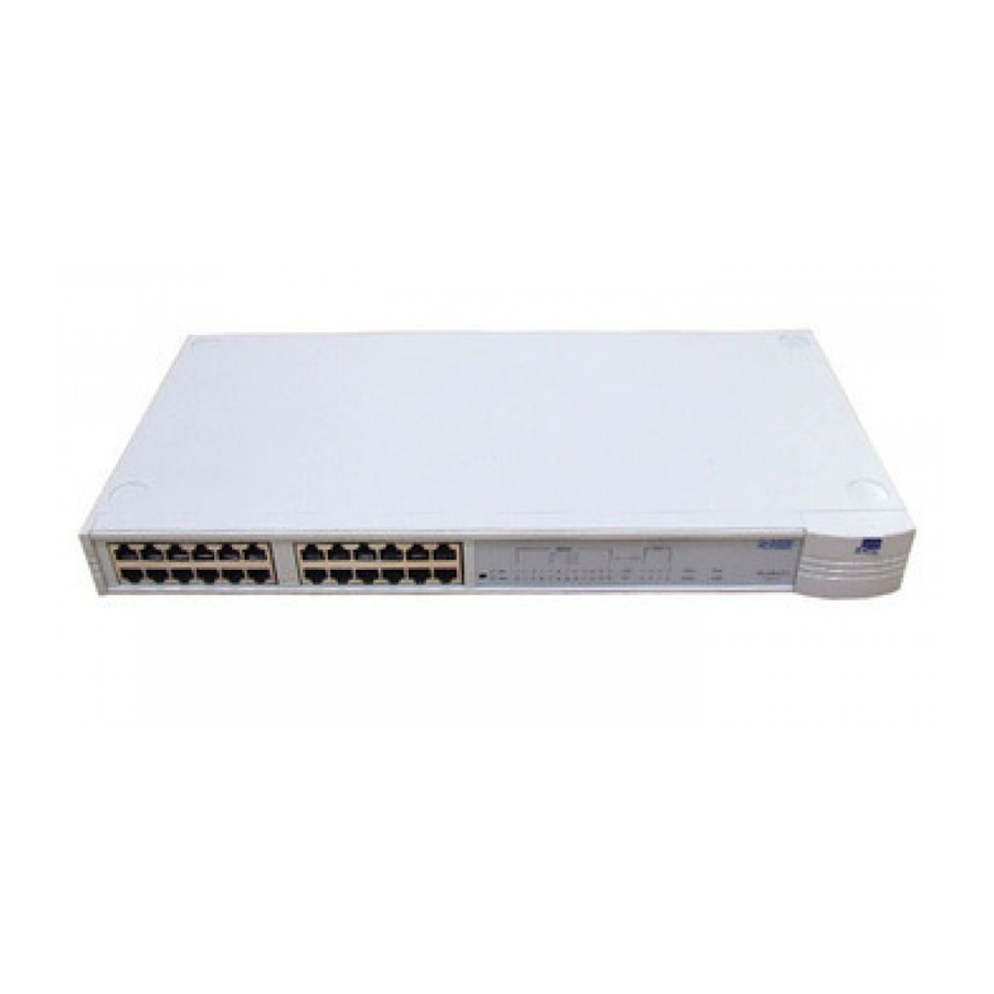
Front Panel
1
12 RJ45 10BASE-T Ports
You can use these ports to connect 10BASE-T DTE (workstations or
other equipment) to the Baseline Switch. The equipment that is
connected to the Baseline Switch must not be set up to operate in
full duplex. Set it up to operate as auto-negotiate or half duplex.
WARNING: RJ45 ports. These are shielded RJ45 data
sockets. They cannot be used as telephone sockets. Only
connect RJ45 data connectors to these sockets.
AVERTISSEMENT: Les ports RJ45. Ceux-ci sont les prises
de courant de données RJ45 protégées. Ils ne peuvent pas
être utilisés comme prises de courant téléphoniques.
Brancher seulement les connecteurs RJ45 de données à ces
prises de courant.
WARNUNG: RJ45 Ports. Hierbei handelt es sich um
abgeschmirte RJ45 Datenbuchsen, die nicht als
Telefonbuchsen verwendbar sind. Nur RJ45
Datensteckverbinder an diese Buchsen anschließen.
Either shielded or unshielded data cables with shielded or unshielded
jacks can be connected to these data sockets.
2
MDI Switch (for port 12)
Ports 1–11 are fixed as MDIX ports so that they can be connected
directly to DTE which have MDI ports using normal 'straight through'
TP cables.
Port 12 is 'switch selectable' using the MDI Switch. The port can be
an MDIX port (to connect directly to DTE like the other ports), or an
MDI port (to connect to other units using a normal 'straight through'
TP cable).
Out
In this position you can connect port 12 to a
workstation or any other DTE using a normal
'straight through' TP cable.
MDIX
In
In this position you can connect port 12 to any
MDIX port on a 10BASE-T unit using a normal
MDI
'straight through' TP cable.
To connect a 10BASE-T unit to the Baseline Switch, connect an MDIX
port on the 10BASE-T unit to port 12 on the Baseline Switch, as
shown below. Ensure that the MDI switch on the Baseline Switch is
IN (MDI). If an MDI/MDIX port is used on the 10BASE-T unit, ensure
that the MDI switch for that port is OUT (MDIX).
3
Traffic LEDs
The Traffic LEDs flash yellow whenever data is received or
transmitted on one of the ports.
If the LEDs do not flash, there are no data being received or
transmitted by those ports. If the unit is receiving data on a port but
the LED does not flash, the LED has failed. Contact your supplier.
4
Status LEDs
The Status LEDs show the state of a port and whether or not the
Link Pulse signal is present on the segment connected to a port:
Green
A 10Mbps Link Pulse signal is being received and the
10BASE-T segment attached to the port is functional.
Yellow
A 100Mbps Link Pulse signal is being received and the
100BASE-TX segment attached to the port (port 13 or
14 only) is functional.
Off
The Link Pulse signal is not being received. Either you
have nothing connected to the port, or there is a
problem:
3
Check that the attached DTE is switched on.
3
Check that the attached transceiver is not faulty.
For a 10BASE-T connection:
3
If it is port 12, check the setting of its MDI switch,
refer to 2. If it is port 14, check the setting of its
MDI switch, refer to 10.
3
Check that there are no more than four repeaters in
series, and that cable lengths do not exceed the
maximum specified in the standard for that medium.
For a 100BASE-TX connection:
3
If it is port 14, check the setting of its MDI switch,
refer to 10.
3
Check that there are no more than two repeaters in
series, and that cable lengths do not exceed the
maximum specified in the standard for that medium.
If these checks do not identify the cause of a problem, it may be
that the switch or the device connected to the port is faulty. Contact
your supplier for further advice.
5
Full Duplex LEDs
The Full Duplex LEDs light green if the 10/100 ports (ports 13 and
14) are operating in full duplex mode (the devices connected to the
ports support auto-negotiation).
If the LEDs are not lit, the ports are operating in half duplex mode
(the devices connected to the ports do not support
auto-negotiation).
6
Power LED
The Power LED lights green to indicate that the unit is powered on.
If it is not lit, and:
None of the ports work
All ports function normally The LED has failed. Contact your
Rear Panel Connections
7
Power Supply
The Baseline Switch automatically adjusts to the supply voltage. Only
use the power cord that is supplied with the Baseline Switch, or a
power cord of the same type.
8
Socket for Redundant Power System
Only connect a 3Com SuperStack II Advanced Redundant Power
System (3C16070) to this socket. A 60W Power Module is required.
For details, follow the installation instructions in the guide
accompanying the Advanced Redundant Power System.
9
Two RJ45 10/100 Ports
You can use these ports to connect 10BASE-T or 100BASE-TX DTE
(workstations or other equipment) to the Baseline Switch. The speed
of the ports is determined automatically when you connect your
equipment.
Either shielded or unshielded data cables with shielded or unshielded
jacks can be connected to these data sockets. The equipment that is
connected to the Baseline Switch must not be set up to operate in
full duplex. Set it up to operate as auto-negotiate or half duplex.
3
The unit is not powered on. There may
be a problem with the fuse within the
power cord's plug.
supplier.