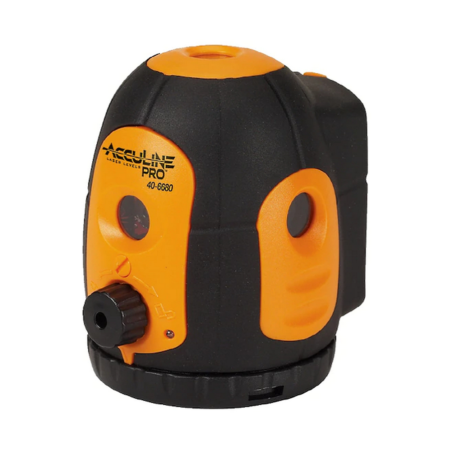
AccuLine 40-6680 Service Manual - Page 12
Browse online or download pdf Service Manual for Laser Level AccuLine 40-6680. AccuLine 40-6680 16 pages. 5 beam laser pointer
Also for AccuLine 40-6680: Instruction Manual (13 pages)

5.
Use the theodolite to mark three vertical lines on the three walls, respectively. All angles between the three vertical lines
are right angles.
6.
Use the theodolite to mark 3 horizontal lines at the intersection of the vertical lines, assuring that they are all at the same
height on the wall.
7.
Mark the three cross points of the three vertical lines and the three horizontal lines as A,B,C, which are the reference
points for the left, face and right laser spot respectively.
8.
Take a high-accuracy instrument and make its plumb-down point be on one line with the down adjacent light point.
9.
Then put a right-angle prism on the bracket. Adjust the angle to make the up laser point emitted by the instrument be
reflected on the wall near the position O;
10. Make the front laser point face the wall. Mark the up and down laser spot reflected through the prism on the wall as
O1 and P1. Then rotate the instrument by 90
11. Take the center point of O1, O2, O3, O4, This center point just is the
reference point for the up laser point. Take the center point of P1, P2, P3,
P4, This center point just is the reference point for the down laser point.
See the illustration to the right.
4.2. Quantifying Accuracy Error
1.
As shown in the figure to the right, put the instrument on the test
platform. Connect with the power, and turn on the Power switch.
2.
Make the plumb-down point be on one line with the down adjacent light
point. The front point faces the vertical line, which B is on.
3.
Observe whether the five centers of the five laser spots are within the
five circles respectively, of which the diameter is 2mm and the centers
are the reference point A, B, C, O and P respectively. If not, the
instrument needs adjusting. (See figure below)
Circle with a diameter of 2mm
The accuracy of the laser point is qualified
Prepared By: Tim Wojo
o
o
, 180
and 270
Center of laser spot
Reference Point
Revision - Date: 0 – 20080430
40-6680 Service Manual
o
clockwise, and mark O2, O3, O4 and P2, P3, P4.
O 1
O
O 2
O 3
Circle with a diameter of 2mm
Center of laser spot
Reference Point
Need adjustment
P1
P4
O 4
P
P2
P3
Page 12 of 16
