Axminster AW12BM User Manual - Page 10
Browse online or download pdf User Manual for Drill Axminster AW12BM. Axminster AW12BM 20 pages. 12mm bench morticer

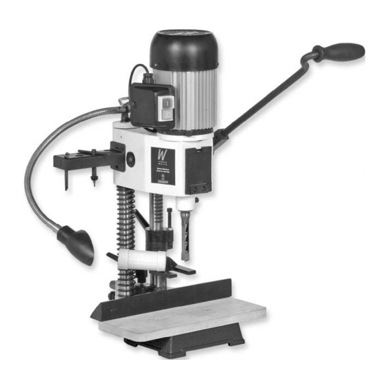
Parts Identification and Description (Continued)
Tool post
Two steel shafts mounted into the rear of the base casting, they are the
columns
'runners' for the headbox. They are 'bridged' at the top to increase accuracy
(See fig 2)
and rigidity, The machine lamp is mounted on the bridging lozenge. The right
hand column has a rack cut in the surface which engages with a pinion in the
headbox assembly to provide the rise and fall action. The double depth stop
collar is also mounted on the right hand side column below the headbox.
The left hand column carries the counterbalance spring.
Headbox
This is the 'morticing machine' and the descriptions of its various
parts and components are detailed as follows:-
Headbox
The main casting to which all the components are attached. The headbox has
casting
two sleeve housings machined at the rear, which allows the casting to be
(See fig 3)
fitted to the Tool Post Columns.
The motor
Standard 240V 50Hz single phase four pole motor rated at 370W, mounted on
(See fig 3)
the top of the headbox.
Auger mounting A 12mm drill chuck that is mounted directly onto the motor shaft. Access for
chuck
the chuck key is via a door in the front of the headbox.
(See fig 3b)
On/Off switch
The switch assembly is mounted in a box which is bolted to the side of the
assembly
Motor. The two button switches are marked with the standard 'O' for stop
(See fig 3a)
and 'I' for start. The assembly is an NVR type so any loss of the supply
during operation, when re-established, will not cause the motor to restart.
Rise and fall
There is a housing machined on each side of the the headbox which mounts
mechanism
a through shaft. A pinion gear is mounted on the shaft inside the headbox
(See fig 1)
and meshes with the rack cut into the tool post column. Driving the pinion
shaft will cause the headbox to rise and fall up and down the tool post
columns. The end of the shaft protruding from the headbox has a castellated
dog mounted over it which is pinned through to prevent slip, through the
centre of the dog is a threaded hole to enable the plunge lever assembly to
be mounted to it.
Plunge lever
The associated part of the rise and fall mechanism is the plunge lever handle
assembly
assembly. This consists of a tube, shaped and bent to provide a handle. The
(See fig 1)
end of the handle which mounts onto the rise and fall shaft has a castellated
dog and a locating boss. There is a through hole in the boss, one end of the
boss is the mating castellated dog that meshes with the dog on the pinion
shaft; the other end is recessed to house the fixing bolt and the retaining
spring. The fixing bolt goes through the boss into the rise and fall shaft,
tensions the spring which holds the castellations engaged. To move the
handle to a different position, disengage the dogs by pulling them apart
(against the spring) move the handle to the desired position, and allow the
spring to re-engage the dogs. There is a grip sleeve that fits over the handle
itself, to provide a firmer grip and some cushioning to the hand.
10
