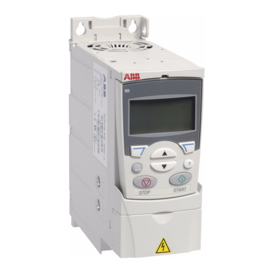
ABB ACS320 series Supplemental Manual - Page 7
Browse online or download pdf Supplemental Manual for Controller ABB ACS320 series. ABB ACS320 series 16 pages. Variable frequency drives in renewaire ventilators
Also for ABB ACS320 series: Installation Instructions (4 pages), Installation Instructions (4 pages)

ANALOG INPUTS TO PROVIDE THE SPEED SIGNAL
Analog inputs are connected as shown below. It may be necessary to scale the response of the VFD to the
analog SPEED signal. See example of VFD Parameter Scaling in Figure 9 (F9).
F4
EXAMPLES OF ANALOG INPUT CONNECTIONS.
WIRING TWO VFDS FOR LEADER-FOLLOWER OPERATION
One VFD can provide the SPEED signal to a second VFD, as shown below.
F5
LEADER-FOLLOWER CONNECTION.
Connect VFDs as shown -
FA VFD will pass the Frequency
(Speed) Signal to the EA VFD.
Use shielded cable and ground
the shield to Terminal 1 on
either VFD
ABB VARIABLE FREQUENCY DRIVES
1.800.627.4499
INSTALLATION
WIRING SCHEMATICS
NOTE: All wiring for analog signals connected to the
VFDs should be double - or single-shielded twisted-pair
cable. Ground the shield at one end of the cable only.
NOTE: Parameters 1501 and 1502 can be used to
scale the Analog Output of the Leader VFD in order to
offset or correct the speed of the Follower VFD.
If the FA VFD is controlled by an analog input signal,
it is likely that the FA VFD's response to the analog
input will need to be scaled, using parameters 1104,
1105, 1301 and 1302. See example of VFD Parameter
Scaling in Figure 9 (F9).
If both VFDs are to run at the same speed, no scaling
parameters need be applied to the EA VFD since it is
controlled as a "Follower".
ABB VFD SUPPLEMENTAL MANUAL
RENEWAIRE.COM
7
