ABB ACS800 Multidrive Hardware Manual - Page 5
Browse online or download pdf Hardware Manual for Controller ABB ACS800 Multidrive. ABB ACS800 Multidrive 20 pages. Asfc switch fuse controller unit for frame r8i inverter modules

Hardware description
What this chapter contains
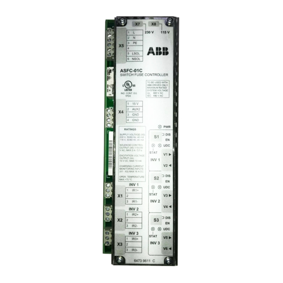
This chapter shows an overview of the ASFC unit and describes the connectors,
settings and LEDs. In addition there is a circuit diagram of frame R8i inverter power
supply circuit and descriptions of the power switch-on and power off sequences.
ASFC unit overview
. 1
1
2
3
X 5
4
5
6
A S . C - 0 1 C
S W I T C H . U S E C O N T R O L L E R
1
2
X 4
3
4
R A T I N G S
S U P P L Y V O L T A G E ( X 5 )
2 3 0 V , 5 0 / 6 0 H z , 4 0 m A
1 1 5 V , 5 0 / 6 0 H z , 8 0 m A
S O L E N O I D C O N T R O L
O U T P U T ( X 5 ) 1 1 5 / 2 3 0
V A C , M A X 2 A / 3 , 5 s
E X C I T A T I O N V O L T A G E
O U T P U T ( X 4 )
1 5 V D C , M A X 1 0 m A
C H A R G I N G
M O N I T O R I N G
( X 1 - X 3 ) M A X 1 6 A D C
O P E R . T E M P E R A T U R E
M A X + 7 0 º C
I N V 1
1
X 1
2
3
I N V 2
1
X 2
2
3
I N V 3
1
X 3
2
3
X 7
X 8
2 3 0 V
1 1 5 V
L
N
P E
L S O L
N S O L
T O
B E U S E D W I T H
A B B D R I V E S O N L Y .
M A X I M U M
R A T E D
S Y S T E M
V O L T A G E
U L :
6 0 0 V A C
I E C : 6 9 0 V A C
1 5 V
A U X 2
G N D
G N D
P W R
D I S
S 1
E N
U D C
S T A T
V 1
I N V 1
V 2
C U R R E N T
I N P U T S
D I S
S 2
E N
U D C
I R 1 +
S T A T
V 3
I N V 2
I R 1 -
V 4
I R 2 +
D I S
S 3
E N
I R 2 -
U D C
S T A T
V 5
I R 3 +
I N V 3
V 6
I R 3 -
6 4 7 3 9 6 1 1
Frame size R8i inverter modules are connected to the drive DC bus
through a switch fuse (type OESL by ABB). The installation is
equipped with a Switch Fuse Controller Unit (ASFC) which controls
the inverter power switch-on and power switch-off. The unit also
protects the charging circuitry by stopping the inverter if switch fuse is
accidentally opened while the inverter is running.
One switch fuse (controlled by one ASFC unit) can provide power
supply for one to three inverter modules. Every inverter module must
have a charging circuit of its own.
The ASFC unit consists of the ASFC board enclosed into a plastic
housing (IP00). The unit can be snapped on onto a standard mounting
rail.
Symbol
Description
X1...X3
Charging circuit connections for Inverter 1, 2 and 3
X4
Switch fuse status monitoring
X5
Connection for ASFC power supply, and operating
voltage for switch fuse locking solenoid
X7, X8
Power supply voltage selection
V1...V6
Fibre optic links to Inverter 1, 2 and 3
S1...S3
Enable switches for charging circuit monitoring
(Inverter 1, 2 and 3)
STAT 1...3
Inverter charging status LEDs (3 pcs)
UDC 1...3
Inverter "ready for start" LEDs (3 pcs)
PWR
ASFC power on LED
5
Hardware description
