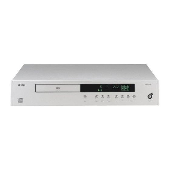
Arcam DiVA CD73 Service Manual - Page 2
Browse online or download pdf Service Manual for CD Player Arcam DiVA CD73. Arcam DiVA CD73 13 pages. Compact disc player

Diva CD73 Circuit description.
Overview
The CD73 is a completely new design platform
for Arcam although the circuit building blocks will
show a passing resemblance to the earlier Diva
designs; the main difference is that the
mechanism control circuitry is now incorporated
within the main circuit board design of the CD
player.
Power supply and Power supply control.
The mains power supply enters the player via the
IEC socket at location SK501 and is filtered by Y
Caps C501 – C502 and X Cap C503, resistor
R501 sits between the Neutral and Positive a.c
supply rails. L501 and L502 filter electromagnetic
noise and reduce stray E.M.F.
SW501 A/B is used to switch the primary feed to
the transformer at location TX501, capacitors
C504 and C505 help to prolong the life expectancy
of the mains switch by reducing contact sparks.
The transformer at location TX501 has multiple
windings and allows for operation from 115v or a
230v mains supply, the mains select switch at
location SW502 connects the duel primaries in
series or parallel depending on the supply
requirements. For 100v operation remove J504
and J503 and fit J502 and J501.
Please note: The Primary of the transformer is
internally fused at 117 degrees C.
Fig 1. Power supply identification and related
components.
Power supply
Associated components
name
AC1 – AC2
On/Off mute circuit.
+11V(U) D.C
DAC card Option at SK203.
+8V D.C
U102 (tray control) U202 (laser optic –
spindle motor). Relay RLY501
analogue supply switch.
-30VF
Filament display grid.
F1 – F2
Filament A.C supply.
+12V(A)
Audio output op-amps U403, U404,
U405 and DAC card option at SK203.
- 12V(A)
Audio output op-amps U403, U404,
U405 and DAC card option at SK203.
+5V(A)=(DAC)
DAC at location U401 and DAC card
option at location SK203.
+5V(D)
Digital control devices U101, U301,
U402, U406, U407, U701 and DAC card
option at SK203.
+3.6V(D)
DSP at location U201, Focus/Tracking
and sledge control at location U101.
By Andy Moore.
We will now breakdown the power supplies down
individually, please refer to Fig 1 for information
on key components driven by the individual
power supply section.
Digital Power supplies
AC1 – AC2 are used to drive the Audio mute
and fast power down control of the Audio output
relay at location RLY 401, Diodes D518 and
D519 rectify the A.C and the following R – C
network and transistor switch stage Q501 – Q505
allowing for the delayed switch on (+ 4 secs) and
instant power down of the Audio output relay the
control line is seen as RLYPWR on the circuit
diagram and should measure +10v D.C at
Jumper PL402.
The +11V(U) supply rail is protected by fuse
FS501 and will only be used directly when an
additional DAC card is added; we use this supply
rail within the CD73 to derive the +8V using U502
and reservoir capacitor C513, the +8V supply
feeds the Tray control and Laser optic drive
packages at location U102 and U202.
The -30VF D.C is derived from the regulator at
location U503 we should see -44V D.C at the
input pin of this device. The power supply forms
the VFD grid on the Display and is current limited
by resistor package R722 (47k ohms).
F1 and F2 provide a 1.5V AC to drive the
filament.
The +11v(U) rail is used to drive the +5(D) power
supply, the supply is regulated by the LM317 at
location U502 and drives the master clock circuit
built around U402 and the SPDIF circuit at
location U407 we also power IR in stage and
Display micro (U701) from this supply.
The +5V(D) rail is further regulated to provide the
+3.6V(D) rail using the LM317 at location U507;
this rail is used to power the DSP at location
U201 and the R.F processor at location U101.
Please note: U507 has been changed to a
LM1086 low dropout regulator, Arcam part
number 5D1086A.
Please note: The above power supplies remain
operational when the CD player is switched to
standby mode from remote control
