digico D5 Live Quick Start Manual - Page 7
Browse online or download pdf Quick Start Manual for Mixer digico D5 Live. digico D5 Live 18 pages. Digital console

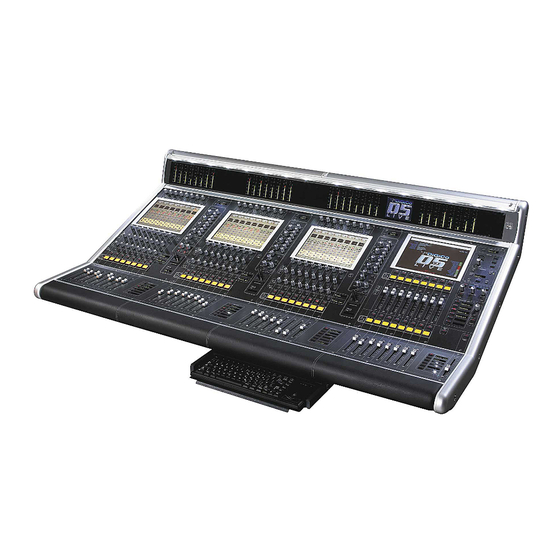
Worksurface
Interface Rack Units and Modules ...............................................
Audio signals are connected to the console via Rack Units. Each Rack Unit is a 19-inch chassis with a
control panel at the bottom. Above this panel are 14 card slots, each of which can accept a Rack Module.
Each Rack is a standard 19" wide, and 9U (353mm) high. The units are 365mm deep, excluding connec-
tors.
Rack Power Supply, Cooling .......................................................
Rack Units have their own mains power connections, 2 x IEC mains inputs per rack, for the dual redundent
supplies. The Rack should NOT be operated with only 1 supply under normal conditions as there is only 1
fan operating. At least 1U (45mm) of space should be left above and below the rack unit to allow ventila-
tion, and to prevent heat transfer from adjacent equipment.
Rack Earthing ................................................................................
The analogue earthing requirements of the Rack unit is similar to those of a conventional large analogue
console. All analogue inputs and outputs are balanced and symmetrical, but not floating, because of their
transformerless design. Installers should use good earthing practice, as with any large audio installation.
Digico can provide copies of AES papers on this subject upon request. -
Rack Control Panel Connections ................................................
The Rack Unit control panel provides connectors as follows:
MADI A IN & OUT (2 x BNC)
MADI B IN & OUT (2 x BNC)
OPTOCORE® A IN & OUT (HMA Optical) (stage rack only)
OPTOCORE® B IN & OUT (HMA Optical) (stage rack only)
WORD SYNC IN & OUT (2 x BNC)
The MADI IN and OUT connections carry audio to/from the Worksurface. There are 2 sets, A & B. The
Coax and Optical (where fitted) are effectively in parallel. A or B are selected in software. Only 1 MADI
connection can be active at 1 time,
The Word Clock Out socket can be used to synchronise other digital devices in the system to the console.
The Word Clock In socket is only used to synchronise the rack system in special stand alone mode. It is
NOT available to sync tthe main system.
The LED indicator on the panel shows the condition of the Rack Unit's power supplies, whether the unit is
synchronised and information of the Rack Status via the 4 buttons and a simple menu system.
Input / Output Slots
Above the panel, the Rack Unit has seven Input and seven Output slots. Each of these slots can be filled
with a different Rack Module, providing an I/O system which is configured according to D5 model.
Rack Modules ................................................................................
There are different Rack Modules for interfacing to different digital and analogue devices. Each Rack
Module carries eight channels of audio.
Page 7
