Digiflex RF120 Installer's Reference Manual - Page 4
Browse online or download pdf Installer's Reference Manual for Transceiver Digiflex RF120. Digiflex RF120 8 pages. Smart rf base station rs485

Receiver Operation
At start up the control panel will configure the receiver
with all the necessary information. The RF120 will
receive information and then send an acknowledge to
the RF device if it supports 2-way communication. For RF
devices that are only one way then no acknowledge is
sent.
Where two or more RF120 receivers are required to
achieve the desired coverage area there can be overlap-
ping areas where multiple receivers detect the same RF
device. The system will determine the receiver with the
strongest signal level and process it accordingly. The
seamless operation and wide coverage area using a LAN
connection allows easy deployment of receivers over the
full 1km control panel LAN length.
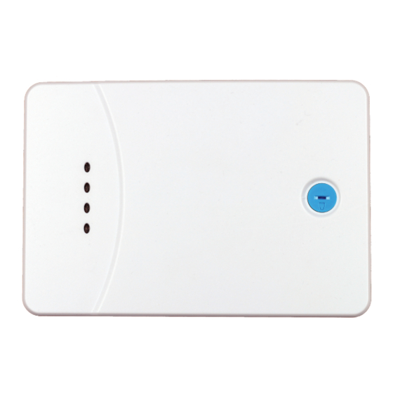
Receiver LED Indicators
The RF120 Base Station includes RED and GREEN LED
indicators which provide visual feedback during system
operation. See Table 3 for information on the indicator
colours and meanings.
Figure 6: RF120 LED Indicators
Position
Colour
1
Red
2
Green
3
Red
4
Green
Page
4
P/N: RF120IRG Rev 1.20
Multiple Receiver Wiring Connection
Module Indicator Lights
Meaning
Blinks each time a packet is sent to a device. In most
RF Transmit
cases this will blink as an acknowledge is sent to a 2-way
device. Blinks each time a valid RF packet is received.
RF Receive
Blinks each time a valid RF packet is received.
Turns on when the receiver has detected a fault. This
Trouble
could be a tamper or jamming levels exceeded. For a
self diagnostic issue the LED will slowly blink.
Blinks each time the system is polled by the control
Status
panel.
Table 3: Receiver LED Indicator Descriptions
Wiring Legend
Control Panel
BLACK
WHITE
LAN +
LAN -
LAN A
LAN B
LAN +
LAN -
LAN A
LAN B
Figure 7: RF120 LAN Wiring
Meaning
E&OE
RED
= LAN +
= LAN -
= LAN A
BLUE
= LAN B
Copyright © 2020
