ABB UMC100.3 Manual - Page 8
Browse online or download pdf Manual for Controller ABB UMC100.3. ABB UMC100.3 18 pages. Modbus rtu communication module, universal motor controller

8
U N I V E R S A L M OTO R C O N T R O L L E R U M C 1 0 0 . 3 | M R P 3 1 . 0 M O D B U S T C P C O M M U N I C AT I O N M O D U L E M A N U A L
Electrical installation
Modbus Connection
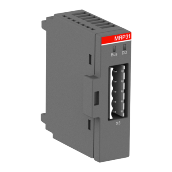
Connect Modbus to X3.
General
Arrange the communication cables as far away from the motor cables as possible. Avoid parallel runs. Use bushings at cable
entries.
—
Connector X3
PIN
Description
1
Bus cable shield. Connected internally to GND via a capacitor.
2
3
GND. Isolated signal ground
4
Data A (inverting)
5
Data B (non inverting)
Bus termination
Bus termination is required to prevent signal reflections from the bus cable ends. The MRP31 Modbus interface module is not
equipped with internal bus termination
Termination with an external termination resistor of 120 h between Data A and Data B should be foreseen on
devices located at bus ends.
Communication settings
The MRP31.0 communication settings are done using a control panel UMC100-PAN plugged onto a UMC100.3 (panel menu:
communication / Modbus RTU) and are copied then automatically to the MRP31.0. After changing communication settings
perform a power cycle.
Master supervision
It is possible to configure a maximal time without telegrams from the master before the UMC100.3 triggers the configured
busfault reaction.
Modbus bus timeout
Time range
0 ... 65535 ms
Default
0 ms (deactivated)
Baudrate
Supported baudrates
1200, 2400, 4800, 9600, 19200, 57600 Baud
Modbus data frame
• 8 E 1
(8 databits, even parity, 1 stopbit)
• 8 O 1
(8 databits, odd parity, 1 stopbit)
• 8 N 2
(8 databits, no parity, 2 stopbits)
• 8 N 1
(8 databits, no parity, 1 stopbit)
Slave address
Allowed addresses
If the MRP31.0 is used with an oldUMC100-FBP.0, then the baud rate is automatically set depending on the
bus address.
See the MRP21-FBP.xxx manual for additional information.
1 ... 247
