ABB 695FI Operating Instruction - Page 3
Browse online or download pdf Operating Instruction for Measuring Instruments ABB 695FI. ABB 695FI 16 pages. Field indicator

CONTENTS
Section
TRANSPORT, STORAGE, HANDLING AND
PRODUCT IDENTIFICATION ......................................... 3
INSTALLATION ............................................................... 4
ELECTRICAL CONNECTIONS ...................................... 4
CALIBRATION PROCEDURE ........................................ 6
DISASSEMBLY AND REASSEMBLY ......................... 12
SPECIFICATION ........................................................... 12
AND "IP" PROTECTION (EUROPE) ............................ 13
GENERAL DESCRIPTION
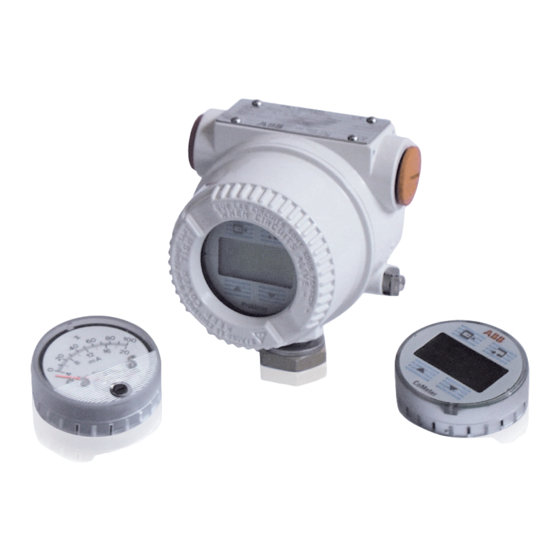
Model 695FI field indicator provides simple and low cost
remote indication of a process variable on an easy to read
display. Various types of display are available:
the 90° scale analog, the LCD digital, ProMeter and CoMeter.
It is on the various meter faceplate that calibration
adjustments are located.
Two types of connection configurations are described. One
involves the indicator coupled to an associated transmitter
terminal block. The other utilizes the indicator as a junction
box in the 4 to 20 mA line between transmitter and receiver.
See the chapter "ELECTRICAL CONNECTIONS" for details.
Product Identification
Ref.B
Safety
marking
plate
Ref.C
Tag number plate
Important - The instrument serial number must always be quoted when making enquiries.
TRANSPORT
After final calibration the instrument is packed in a carton
Page
(Type 2 of ANSI/ASME N 45.2.2-1978) intended to provide
protection from physical damage.
...... 3
HANDLING
The instrument does not require any special precautions
during handling although normal good practice should be
observed.
STORAGE
The instrument does not require any special treatment if
stored as despatched and within the specified ambient
conditions level (Temperature from -40 ÷ +85°C / -40 to 185°F,
0÷100% RH of humidity). There is no limit to the storage pe-
riod, although the terms of guarantee remain as agreed with
the Company and as given in the order acknowledgement.
PRODUCT IDENTIFICATION
The instrument is identified by the plates shown below. The
Nameplate provides information concerning the product
code, the input signal, the product serial number (see Ref. A).
Please refer to this number when making enquiries.
The Safety Marking plate provides information of Ex pro-
tection; it is affixed only when the indicator is required for
hazardous area installation (see Ref. B).
The Tag plate provides the customer tag number and the
calibration range (see Ref. C) .
Ref.A
Nameplate
- 3 -
