Digilent PmodBTN 410-077 Reference Manual
Browse online or download pdf Reference Manual for Control Unit Digilent PmodBTN 410-077. Digilent PmodBTN 410-077 2 pages.

PmodBTN™ Reference Manual
Revised May 24, 2016
This manual applies to the PmodBTN rev. A
Overview
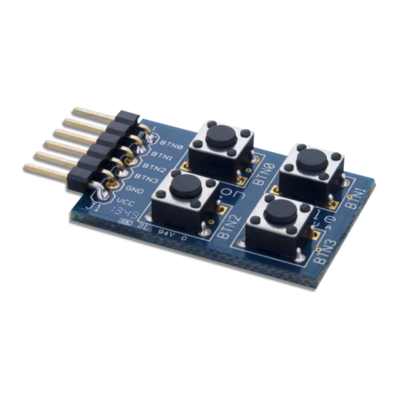
The Digilent PmodBTN gives users four momentary push-buttons for easy user inputs for the system board.
The PmodBTN.
1
Functional Description
The PmodBTN utilizes analog filters consisting of two resistors and a capacitor to absorb and smooth out any signal
bounces that naturally occur when pressing a button. The smoothed out voltage signal is then fed to an inverting
Schmitt-trigger which will then report a logic high voltage to the system board when a button is pressed or a logic
low voltage when the button is not being pressed.
2
Interfacing with the Pmod
The PmodBTN communicates with the host board via the GPIO protocol. For this Pmod, it will only ever send data
to the system board and ignore any signals that it might receive from the system board.
Each button is equipped with its own filter, Schmitt-trigger, and data line so that each button can be pressed
independently of each other. Users may also press the buttons simultaneously for up to 16 different input
combinations.
A pinout description and diagram of the PmodBTN are provided below:
DOC#: 502-077
Other product and company names mentioned may be trademarks of their respective owners.
Features include:
Four momentary pushbuttons
Debouncing filters
Inverting Schmitt Triggers
Small PCB size for flexible designs 1.2" ×
0.8" (3.0 cm × 2.0 cm)
6-pin Pmod connector with GPIO interface
Follows
Specification
Copyright Digilent, Inc. All rights reserved.
1300 Henley Court
Pullman, WA 99163
509.334.6306
www.digilentinc.com
Digilent Pmod Interface
Type 1
Page 1 of 2
