FIAMA F20 User Manual And Maintenance - Page 4
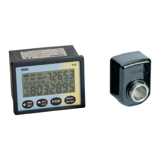
Browse online or download pdf User Manual And Maintenance for Monitor FIAMA F20. FIAMA F20 8 pages. Display with internal battery power supply and hollow shaft rotative transducer
Also for FIAMA F20: User Manual And Maintenance (7 pages)
Display for magnetic band
Sensor mounting
The sensor has be mounted according to the following draw, and keeping the indicated tolerances.
For the optimal system functioning its is necessary that the distance between the sensor and the magnetic
band is not over 1mm of the useful stroke.
MAGNETIC BAND
(
PLASTIC FERRITE SIDE TOWARD THE
SENSOR
N.B. if the distance between the sensor and the magnetic band is over 1mm on the display appears
,and the measured value is wrong.
Programming
To step into the parameter programming press key PGM fino a che apparirà sul display la scritta
press 2 times key RESET
(digit selection), set out password 0273 and confirm with RESET
increase) and
wrong set-out of password it goes out of the programming.
The parameters that have to be set can be run with key
value to be displayed for 100mm of sensor displacement,
number of decimal digits,
count direction,
keys opening mode
displacement of origin,
not used.
To enter into the modification of the selected parameter press two times
value) and with keys
To go out of the programming press
Value to be displayed for 100 mm of sensor displacement
This parameter together with the following allows the programming of the value on the display for a certain
displacement of the sensor. It means that is necessary to set the value which has to be displayed
corresponding to a displacement of the sensor on the magnetic band of 100mm.
The Factory value is
VISUAL
decimal resolution.
The range allowed is from 0,000001 to 9999999 with setting of decimal point position that is, after
programming of the last digit on the left, pressing key
be moved to the wanted position. Confirm with RESET
Number of decimal digits
It is the number of decimal digits to visualize on the display, range allowed from 0 to 5.
Example 1: for each 100 mm of sensor desplacement will have a displacement on the machine of 50, set
=
50 and
Example 2: for each 100 mm of sensor desplacement on display has to appear 12,3. Set
= 000012,3 e
Data: 13/01/16
)
/
ENTER
and appear 4 zeroes, the first on the right is blinking, with keys
and
set the wanted value to be confirmed with
.
=100.0, which is the necessary value to read the displacement in millimetres with
=
0.
= 1.
±3°
±3°
and in order of appearance they are:
will blink the decimal pinpoint and with key
/
.
ENTER
file: F20_ing.doc
/
ENTER
. . In case of
(one time displays only the
RESET
.
RESET
F20
±3°
, now
(digit
it can
pag 4/8