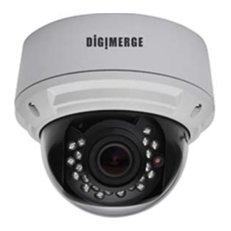
Digimerge DPV24DL Instruction Manual - Page 13
Browse online or download pdf Instruction Manual for IP Camera Digimerge DPV24DL. Digimerge DPV24DL 14 pages. Ultra resolution day & night ir dome camera
Also for Digimerge DPV24DL: Specifications (2 pages), Instruction Manual (14 pages)

CAMERA ADJUSTMENT
LL
PHASE
RETURN
SYNC
INT / LL
Video synchronization displayed
INT(Internal) or LL (Line Lock)
Note: Shows INT with DC only model.
And LL setting for camera model
when connected to a AC supply.
PHASE:
000-524
Adjust the phase in the vertical direction when the line
lock mode is available.
• CAMERA RESET
This will reset all settings for all menus to manufacturer
defaults. This allow you to return to shipped settings
from the manufacturer.
EXIT / SAVE ALL
• EXIT
Exit OSD menu.
• SAVE ALL
Saves the settings to camera
-20-
326
TROUBLE SHOOTING
Refer to the following table if you are experiencing trouble with your camera.
Contact an authorized technician if the table does not provide you with a
solution to the trouble.
Nothing appears on the screen.
Check that the power cord and line connection between the camera and monitor are connected properly.
Check that you have properly connected VIDEO cable to the camera VIDEO output jack.
The image on the screen is dim.
Is lens stained with dirt? Clean lens with soft, clean cloth.
Adjust the monitor contrast & brightness controls
Re-position the camera if necessary.
The image on the screen is dark.
Adjust the contrast feature of the monitor.
If you have an intermediate device, set the 75 / Hi-z properly.
The camera is not working properly, and the surface of the camera is hot.
Check that you have properly connected the camera to an appropriate power source.
IR LED's don't appear to be working (not glowing red in the dark)
Ensure that the power provided to the camera at the camera end meets the power consumption
requirements as per the camera speci cations.
The Motion Detection function does not work.
Check that MOTION DET in SETUP 2 menu is 'ON' for the selected area.
Enable Block display ON will show a visual indication on the display output for the detected areas.
Color is not correct.
Check the setting of WHITE BAL SETUP menu.
Under certain incandescent lighting,some color shifting may take place.
This is normal due to sensitivity to IR light
When the resistance value of copper wire is at [20˚C(68˚F)]
Copper wire size (AWG)
#24(0.22mm
2
)
#22(0.33mm
Resistance ( /m)
0.078
0.050
Voltage Drop (V/m)
0.028
0.018
As shown in the table above, voltage decreases as the wire gets longer. Therefore use of
an excessively long adaptor output line for connection to the camera may affect the
performance of the camera.
*Standard voltage for camera operation : AC 24V ±10% or DC 12V ±10%
*There may be some deviation in voltage drop depending on the type of wire and the manufacturer.
Notes
• Be sure to connect power only after all the installation is complete.
• Use the UL listed, CLASS 2 power transformer for AC24v adaptor.
-21-
2
)
#20(0.52mm
2
)
#18(0.83mm
2
)
0.030
0.018
0.011
0.006
