BYE BIKE BB01-49210-00-810 Assembly Instructions - Page 2
Browse online or download pdf Assembly Instructions for Bicycle Accessories BYE BIKE BB01-49210-00-810. BYE BIKE BB01-49210-00-810 2 pages. Anti-theft system
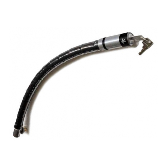
SUPPLIED PARTS
1. Anti-theft system
2. Handlebar linkage
3. Rear linkage
4. Rear bracket
5. Anti-teft system shock absorber support
6. ULS M6x16 Screw (2 units)
7. Self-locking M6 Nut with washer
8. Self-locking M10 Nut
9. Body guard
1.
2.
3.
6.
7.
ASSEMBLY INSTRUCTIONS
A. Cut the end of the left rubber handle using a cutter or
similar tool.
B. Assembly and insert the handlebar linkage (2) with
expansive plug inside the handlebar and tighten with an
Allen wrench.
C. Remove the top nut of the rear left shock-absorver,
introduce the anti-theft system shock absorver bracket (5)
and install the provided M10 nut (9).
D. Remove the rear carrier/handle - motorcycle body
screw (*) and nut (*).
E. Place the rear bracket (4) above the rear carrier/handle
bracket. Fix the installation using the original screw (*)
and nut (*) in the left hole and the provided M6x16 screw
(6) and M6 nut (7) into the center hole. If the rear
carrier/handle does not present the mounting hole, drill a
new hole (diameter 5mm) using the bracket as a guide.
F. Install the rear linkage (3) at the right hole of the
assembly described in section 5 using a M6x16 screw (6).
Fix it with threadlocker.
G. Install the anti-theft system (1) on the linkage provided
in the frame of the motorcycle. Introduce the anti-theft
system with it's head pointing down and left. Turn it
clockwise.
H. Place the body guard (9) at the upper end of the lower
left cover to protect it from rubbing against the antiteft
system.
I. Ensure that the anti-theft system works correctly and
that it rests in the correct position when not used.
COMPONENTES SUMINISTRADOS
1. Sistema antirrobo
2. Enganche manillar
3. Enganche posterior
4. Pletina de soporte posterior
5. Soporte amortiguador
6. Tornillo ULS M6x16 (2 unidades)
7. Tuerca autoblocante con arandela M6
8. Tuerca autoblocante M10
9. Protector de la carrocería
4.
5.
8.
9.
INSTRUCCIONES DE MONTAJE
A. Cortar con un cutter o similar el extremo del puño de
goma izquierdo.
B. Montar e introducir el enganche del manillar (2) con taco
expansivo en el interior del manillar y apretarlo con una llave
allen hasta que quede sujeto firmemente.
C. Retirar la tuerca superior de la suspensión posterior
izquierda, introducir el soporte del sistema antirrobo (5) y
colocar la tuerca M10 (8).
D. Retirar el tornillo (*) y la tuerca (*) que une la parte
izquierda de la parrilla de transporte o asidero y la carrocería.
E. Colocar la pletina (4) por delante de la fijación de la
parrilla/asidero. Fijar la instalación mediante el tornillo (*) y la
tuerca (*) originales en el agujero izquierdo del montaje y el
tornillo M6x16 (6) y la tuerca M6 (7) en el agujero central del
montaje. En caso de que la parrilla/asidero no dispusiera del
agujero para el montaje de la pletina, perforar el agujero
utilizando un taladro (Ø 5mm) y la pletina provista como guia.
F. Instalar el sistema de enganche posterior (3) en el extremo
derecho del montaje descrito en el punto 5. Apretarlo
firmemente con el tornillo M6x16 (6) y asegurar la fijación
con una gota de fijador de roscas.
G. Introducir el sistema antirrobo (1) en el anclaje provisto
en el chasis de la motocicleta con la cabeza del sistema
antirrobo apuntando hacia abajo y a la izquierda. Girar el
sistema antirrobo en el sentido de las agujas del reloj para
dejarlo instalado.
H. Coloque el adhesivo protector de la carrocería (9) en el
extremo superior de la tapa inferior izquierda para protegerla
del roce del sistema antirrobo.
I. Compruebe que el sistema antirrobo funciona
correctamente y que descansa en la posición adecuada
cuando no es usado.
A B
2
D
E
F
7
*
G
1
H
C
8
5
6
4
3
6
*
I