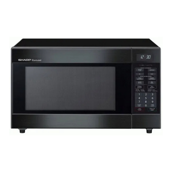
Sharp Carousel R-395N Service Manual - Page 19
Browse online or download pdf Service Manual for Microwave Oven Sharp Carousel R-395N. Sharp Carousel R-395N 28 pages. Microwave oven
Also for Sharp Carousel R-395N: Operation Manual And Cookbook (40 pages)

[3] POWER TRANSFORMER REMOVAL
1. REMOVAL
1. CARRY OUT 3D CHECKS.
2. Disconnect wire leads (primary) from the power transformer.
3. Disconnect the high voltage fuse from the power transformer.
4. Disconnect the filament leads from the magnetron and the high
voltage capacitor.
5. Remove four (4) screws (two (2) screws from the upper side and
two (2) screws from bottom side) holding transformer to bottom
plate.
6. Remove transformer from bottom plate.
[4] HIGH VOLTAGE RECTIFIER ASSEMBLY, HIGH VOLTAGE FUSE AND HIGH VOLTAGE
CAPACITOR REMOVAL
1. CARRY OUT 3D CHECKS.
2. Disconnect the high voltage fuse from the power transformer.
3. Disconnect the high voltage wire of high voltage rectifier assembly
from the magnetron.
4. Disconnect the filament lead (short one) of the power transformer
from the high voltage capacitor.
5. Remove the one (1) screw holding capacitor holder to bottom plate.
6. Remove one (1) screw holding high voltage rectifier assembly to
capacitor holder.
[5] MAGNETRON REMOVAL
1. REMOVAL
1. CARRY OUT 3D CHECKS.
2. Disconnect all wire leads from magnetron.
3. Remove the one (1) screw holding the chassis support to the mag-
netron.
4. Release the chassis support from the hole of the oven cavity front
flange.
5. Remove the two (2) screws holding air duct to magnetron and oven
cavity top plate.
6. Remove the air duct from oven.
7. Carefully remove the four (4) screws holding magnetron to
waveguide flange.
8. Remove magnetron with care so that magnetron antenna is not hit
by any metal object around antenna.
9. Now, the magnetron is free.
[6] POSITIVE LOCK CONNECTOR (NO-CASE TYPE) REMOVAL
1. CARRY OUT 3D CHECKS.
2. Push the lever of positive lock connector.
3. Pull down on the positive lock connector.
CAUTION: WHEN CONNECTING THE POSITIVE LOCK CONNEC-
TORS TO THE TERMINALS, CONNECT THE POSITIVE
LOCK SO THAT THE LEVER FACES YOU.
2. RE-INSTALL
1. Rest transformer on the bottom plate with its primary terminals
toward the oven face plate.
2. Secure transformer with four (4) screws (two (2) screws from the
upper side and two (2) screws from bottom side) to bottom plate.
3. Reconnect wire leads (primary) to power transformer and filament
leads of transformer to magnetron and high voltage capacitor. And
reconnect the high voltage fuse to the power transformer. Refer to
"PICTORIALDIAGRAM".
4. Reinstall outer case and check that oven is operating properly.
7. Disconnect rectifier terminal from capacitor.
High voltage rectifier assembly is now free.
8. Disconnect the high voltage fuse from the capacitor.
The high voltage fuse is now free.
9. Remove capacitor holder. Capacitor is now free.
CAUTION: WHEN REPLACING HIGH VOLTAGE REC-TIFIER AND
HIGH VOLTAGE CAPACITOR,GROUND SIDE TERMINAL
OF
THE
SECUREDFIRMLY WITH A GROUNDING SCREW.
2. REINSTALLATION
1. Reinstall the magnetron to waveguide flange with the four (4)
screws.
2. Reinstall the air duct to the oven cavity top plate and the magnetron
with two (2) screws.
3. Insert the end of the chassis support into the hole of the oven cavity
front flange.
4. Hold the other end of the chassis support to the magnetron with the
one (1) screw.
5. Reconnect the wire leads to the magnetron. Refer to "PICTORIAL
DIAGRAM".
6. Reinstall outer case and check that the oven is operating properly.
CAUTION: WHEN REPLACING MAGNETRON, BESURE THE R.F.
GASKET IS IN PLACE ANDMOUNTING SCREWS ARE
TIGHTENEDSECURELY.
Positive lock¨
connector
Lever
Figure C-1. Positive lock, connector
11 – 2
HIGHVOLTAGE
RECTIFIER
Terminal
1
Push
2
Pull down
R395N(S)
MUST
BE
