Digital Alert Systems 637 Instruction Manual - Page 9
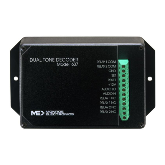
Browse online or download pdf Instruction Manual for Media Converter Digital Alert Systems 637. Digital Alert Systems 637 16 pages. Dual tone decoder

Audio Input Connection:
The audio input is connected at pins '6' and '5' (circuit common). The 3185E is factory set at 10 k input
impedance; unbalanced. This audio input may be changed by the customer to have a 600
instead of 10 kΩ, and also to be balanced instead of unbalanced. Consult the CUSTOMER OPTION
section for more explanation.
'Set' Input Connection:
The 'Set' input is connected at pin 'D', and when pulsed to circuit common will energize the output relay.
The output relay will remain energized until the proper 'OFF' code is received or the 'Reset' input is
pulsed to ground. This input is level sensitive and requires a minimum pulse width of 20 msec. to circuit
common to activate or de-activate the output relay. The 'Set' input has precedence over all functions
except 'Reset'.
If the 3185E's 'Set' input is pulsed to circuit common while decoding a code sequence it will clear
previous valid digit(s) decoded after the 'Set' input returns to a 'high' state.
'Reset' Input Connection:
Momentarily connecting pin 'E' to circuit common will cause the 3185E to reset. This input is level
sensitive and requires a minimum pulse of 20 msec. to circuit common to reset the card. The 'Reset'
input dominates over all other functions.
NOTE: The 3185E will ignore all commands or code sequences until the 'Reset' input is removed from
circuit common.
Relay Output Connections:
The 3185E provides a dual Form C relay output. The output relay will energize whenever the
preprogrammed 'ON' code sequence is received or the 'Set' input is momentarily connected to circuit
common. If the output relay is set to 'momentary', the output relay will activate approximately 40ms after
the last valid digit is received and stay on as long as the last valid digit is present. If the output relay is
set to 'latching', the output relay will remain energized until the programmed 'OFF' code sequence is
received or the 'Reset' input is momentarily connected to circuit common.
The dual Form C relay output connections are shown below:
RELAY OUTPUT
1 FORM C
1 FORM C
Power Supply Input:
The power supply input is connected to pins '8' (+12 VDC) and '3' (circuit common). The 3185E requires
a power supply capable of providing 50mA minimum, and regulation of the +12 volt, ±10 %.
NORMALLY
CLOSED
COMMON
CONTACT
CONTACT
1
9
A
K
TABLE 1
NORMALLY
OPEN
CONTACT
10
L
termination
9
