Siemens 3AH Instructions Manual - Page 10
Browse online or download pdf Instructions Manual for Industrial Equipment Siemens 3AH. Siemens 3AH 38 pages. Vacuum circuit breaker operator module
Also for Siemens 3AH: Instructions, Installation, Operation, Maintenance (33 pages), Installation Operation & Maintenance (20 pages)

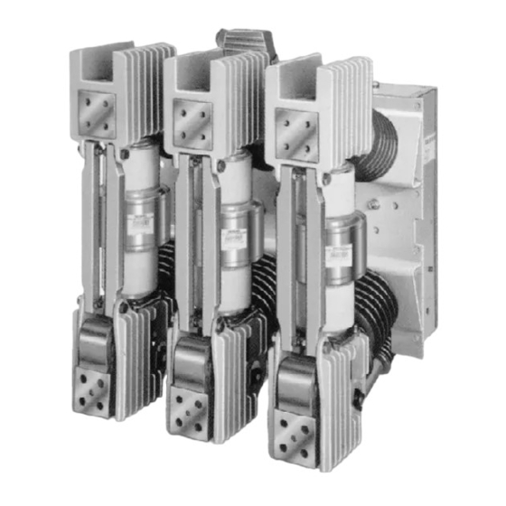
Vacuum Interrupter/Operator Description
Construction (Figures 1 , 2, 5, 6a and 6b)
Each of the circuit breaker poles a re fixed to the rear of the
operating mech a n ism housing by two cast-resin insulators.
The i n sulators also connect to the upper and lower pole
supports which in turn support the ends of the vacuum inter
rupter. The pole supports are aluminum castings ( 1 200A a n d
2000A) or copper castings (3000A). Primary stud extensions
may be attached d irectly to the uppe r and lower pole sup
ports.
The energy-stori ng mecha nism and all the control and
actuating d evices are instal led in the mechan ism housing.
The mecha nism is of the spring stored energy type and is
mech a n ically and electrically trip free.
The close-open i n d icator, closing spring charge ind icator,
a n d the operation counter are located on the front of the
mechanism housing.
The control connector for the control and sig nalling cables is
a multi contact plug.
Heoo ---- -- --,
Poe
Argled Lewr
Figure 5 . Pole Assembly
Circuit Breaker Pole (Figure 5)
The vacuum interrupter is rig idly connected to the pole head
by its post insulator. The lower part of the vacuum interrupt
er is stabilized against lateral forces by a centering ring on
the pole bottom. The externa l forces due to switch ing opera
tions and the contact pressure are absorbed by the struts.
Current-Path Assembl y (Figure 5 )
T h e current-path assembly consists of t h e pole h e a d , the
stationary contact, and the moving contact, which is con
nected to the pole bottom by a term i n a l clamp and a flexible
connector.
Vacuum Interrupter (Figure 5 )
T h e moving contact motion is a l i g n e d and stabil ized b y a
guide bushing. The metal bellows fol l ows the travel of the
contact and seals the vacuum interrupter against the sur
rounding atmosphere.
Switching Operation (Figures 5 and 6a)
When a closing command is initiated, the closing spring
(62). which was previously charg ed by h a n d or by the mo
tor, a ctuates the moving contact through the jack shaft (63),
lever, contact pressure spring (49), insulating coupler (48),
and angled lever.
The forces that occur when the action of the insulating cou
pler (48) is converted into the vertical action of the moving
contact are a bsorbed by the guide l in k, wh ich pivots on the
pole bottom and the eye bolt.
During closing, the opening spring (64) (Figure 6a) and the
contact pressure springs (49) are charged and latched by
pawl (64.2) (Figure 6b) . The closing spring (62) (Figure 6a) of
the motor-operated circuit breaker is recharged immed iately
after closi n g .
I n t h e closed state, t h e necessary contact pressure is main
tained by the contact pressure spring (49) and the atmo
spheric pressure. The contact pressure spring automatically
compensates for arc erosion, which is very small.
When a opening command is g iven, the energy stored in
the opening and contact pressure springs (49) is released
by pawl (64.2) (Figure 6b) . The ope n i n g sequence is similar
to the closing sequence. The residual force of the opening
spring arrests the moving contact in the open position.
Operating Mechanism
The operating mecha-
nism is comprised of the mecha nical and electrical compo
nents required to:
1. Charge the closing spring with sufficient potential energy
to close the circuit breaker a n d to store opening energy
in the opening and contact pressure springs.
2. Mech a n isms to release closing and opening actions.
3. Means of transmitting force and motion to each of three
pole positions.
4. Operate all these functions automatically through electri
cal charg ing motor, cutout switches, antipump relay,
close coil, open coil, a n d auxiliary switch.
5. Provide indication of the circuit breaker status (open/
closed), spring condition (charged/discharged). and
number of operations.
8
