Siemens SINAMICS G120 Hardware Installation Instructions

Browse online or download pdf Hardware Installation Instructions for Industrial Equipment Siemens SINAMICS G120. Siemens SINAMICS G120 2 pages. Using blocksize converters in marine applications
Also for Siemens SINAMICS G120: Getting Started (46 pages), Operating Instructions Manual (32 pages), Getting Started (30 pages), Installation Instructions And Owner's Manual (2 pages), Installation Instructions (2 pages), Installation Instructions (2 pages), Compact Operating Instructions (32 pages), Manual (42 pages), Getting Started (50 pages), Device Manual (34 pages), Quick Install Manual (2 pages), Application Description (50 pages), Compact Operating Instructions (2 pages), Manual (31 pages), Applications Manual (34 pages), Compact Operating Instructions (2 pages), Compact Operating Instructions (2 pages)
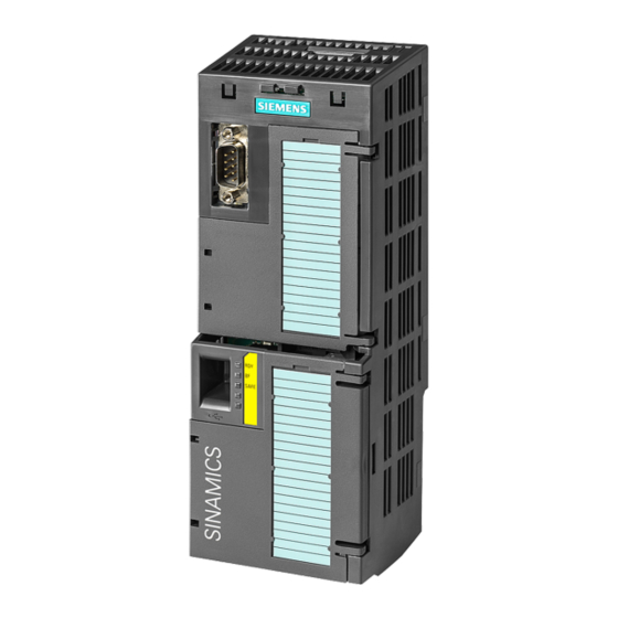
Siemens SINAMICS G120 Hardware Installation Instructions
Fitting the Brake Modules (PM240 / PM250 / PM260)
Frame size F
Frame size GX
Brake Relay (with 230 V AC or 400 V AC supply)
Rectifier module
e.g. in the motor terminal box
Mean time to failure when controlling Siemens brake is 500,000 operations.
Mit Siemens-Bremsen werden im Mittel 500 000 störungsfreie Schaltvorgänge erreicht.
Compact Hardware Installation Instructions
Fitting the Brake Modules (PM240-2 / PM240P-2 / PM250)
PM240-2/PM240P-2
Side-mounted Brake Module
Connection diagrams
Safe Brake Relay (with 24 V DC external supply)
Brake Relay (with 24 V DC external supply)
PM240-2 / PM250 FSD/FSE
Rear-mounted Brake Module
Dimensions
Brake Relay Module
48.4 mm
29.7 mm
2.97 mm
68.8 mm
59 mm
Ø4.5 mm
67.9 mm
SINAMICS G120
Brake Relay and Safe Brake Relay
PM240-2 / PM250 FSF
Rear-mounted Brake Module
Safe Brake Relay Module
48.4 mm
21.2 mm
11.8 mm
68.8 mm
59 mm
Ø4.5 mm
63.4 mm