Siemens SINAMICS G130 Operating Instructions Manual - Page 11

Browse online or download pdf Operating Instructions Manual for Industrial Equipment Siemens SINAMICS G130. Siemens SINAMICS G130 26 pages. Line filter
Also for Siemens SINAMICS G130: Operating Instructions Manual (24 pages), Operating Instructions Manual (46 pages), Operating Instructions Manual (24 pages), Operating Instructions Manual (31 pages), Operating Instructions Manual (30 pages), Operating Instructions Manual (28 pages), Operating Instructions Manual (30 pages), Operating Instructions Manual (22 pages), Operating Instructions Manual (28 pages), Operating Instructions Manual (30 pages), Operating Instructions Manual (34 pages), Operating Instructions Manual (46 pages), Operating Instructions Manual (26 pages), Operating Instructions Manual (26 pages), Operating Instructions Manual (28 pages), Operating Instructions Manual (42 pages), Operating Instructions Manual (46 pages), Operating Instructions Manual (24 pages), Operating Instructions Manual (24 pages), Operating Instructions Manual (30 pages), Operating Instructions Manual (42 pages), Operating Instructions Manual (38 pages), Operating Instructions Manual (46 pages), Operating Instructions Manual (28 pages), Operating Instructions Manual (22 pages), Operating Instructions Manual (24 pages)
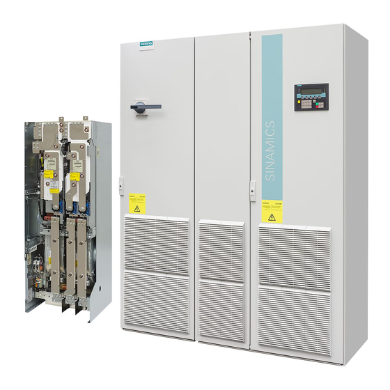
Siemens SINAMICS G130 Operating Instructions Manual

General information

The terminal module TM150 is a DRIVE-CLiQ component for temperature evaluation. The
temperature is measured in a temperature range from -99 °C to +250 °C for the following
temperature sensors:
● PT100 (with monitoring for wire breakage and short-circuit)
● PT1000 (with monitoring for wire breakage and short-circuit)
● KTY84 (with monitoring for wire breakage and short-circuit)
● PTC (with short-circuit monitoring)
● Bimetallic NC contact (without monitoring)
For the temperature sensor inputs, for each terminal block the evaluation can be
parameterized for 1x2-wire, 2x2-wire, 3-wire or 4-wire. There is no galvanic isolation in the
TM150.
The TM150 is mounted in the control cabinet and can be snapped on to a standard mounting
rail (EN 60715).
The TM150 contains the following interfaces:
Table 2- 1
Type
DRIVE-CLiQ interfaces
Temperature sensor inputs
Electronic power supply
2.1

Safety information

The 50 mm clearances above and below the components must be observed.
CAUTION
Temperature sensors must always be connected up using shielded cables. The cable
shield must be connected to the ground potential at both ends through a large surface area.
Temperature sensor cables that are routed together with the motor cable must be twisted in
pairs and shielded separately.
Terminal Module 150 (TM150)
Operating Instructions, 03/2012, A5E03758735A
Overview of the TM150 interfaces
WARNING
Quantity
2
6/12
1
2
9