Siemens SINAMICS G130 Operating Instructions Manual - Page 17

Browse online or download pdf Operating Instructions Manual for Industrial Equipment Siemens SINAMICS G130. Siemens SINAMICS G130 26 pages. Line filter
Also for Siemens SINAMICS G130: Operating Instructions Manual (24 pages), Operating Instructions Manual (26 pages), Operating Instructions Manual (46 pages), Operating Instructions Manual (24 pages), Operating Instructions Manual (31 pages), Operating Instructions Manual (30 pages), Operating Instructions Manual (28 pages), Operating Instructions Manual (30 pages), Operating Instructions Manual (22 pages), Operating Instructions Manual (28 pages), Operating Instructions Manual (30 pages), Operating Instructions Manual (34 pages), Operating Instructions Manual (46 pages), Operating Instructions Manual (26 pages), Operating Instructions Manual (28 pages), Operating Instructions Manual (42 pages), Operating Instructions Manual (46 pages), Operating Instructions Manual (24 pages), Operating Instructions Manual (24 pages), Operating Instructions Manual (30 pages), Operating Instructions Manual (42 pages), Operating Instructions Manual (38 pages), Operating Instructions Manual (46 pages), Operating Instructions Manual (28 pages), Operating Instructions Manual (22 pages), Operating Instructions Manual (24 pages)
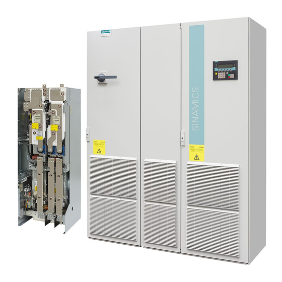
Siemens SINAMICS G130 Operating Instructions Manual

Mechanical installation

When the line filter is installed in a cabinet, it must be positioned directly beside the Power
Module.
The line reactor must be positioned between the line filter and Power Module. Cabling must
be kept as short as possible.
To prevent interference being injected into the interference-suppressed line cable (this can,
in some cases, nullify the effects of the line filter), the line cable to the line filter must be
routed separately from other cables.
The housing of the Power Module and line filter must be connected with low resistance for
high-frequency interference currents. This can be achieved by installing the Power Module
and line filter on the same mounting plate. The Power Module and line filter must be
connected to the mounting plate with the greatest possible surface area. The best solution
here is to use a metallic, bare, oil-free mounting plate (e.g. made of stainless steel or
galvanized sheet-steel) because the entire contact surface establishes the electrical contact.
If a painted mounting plate is used, the screw positions for the Power Module and line filter
must free of paint to ensure electrical contact with the mounting plate.
The motor must always be connected using a shielded cable. The shield must be applied to
the motor and Power Module with the greatest possible surface area.
The ground wire for the motor must be fed directly back to the Power Module.
Line filter
Operating Instructions, 04/2014, A5E00331460A
3
17