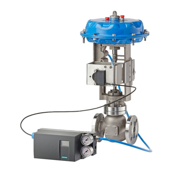
Electropneumatic positioners
SIPART PS2
Technical specifications
SIPART PS2 PA
SIPART PS2 PA
Communication
C2 connections
Device profile
Response time to master message
Device address
PC parameterizing software
Connections
• Electric
• Pneumatic
External position sensor
(potentiometer or NCS; as option) with
the following max. ratings
• U
o
• Io (static)
• I
(short-time)
s
6
• P
o
• Maximum permissible external ca-
pacitance C
o
• Maximum permissible external in-
ductance L
o
6/12
Siemens FI 01 · 2009
© Siemens AG 2008
Basic device
Basic device
without Ex protection
with Ex d protection
(flameproof casing)
Layers 1 and 2 according to PROFIBUS PA, transmission technique according to IEC 1158-2;
slave function; layer 7 (protocol layer) according to PROFIBUS DP,
EN 50170 standard with the extended PROFIBUS functions
(all data acyclic, manipulated variable, feedbacks and status also cyclic)
Four connections to master class 2 are supported,
automatic connection setup 60 s after break in communication
PROFIBUS PA profile B, version 3.0, more than 150 objects
SIMATIC PDM; supports all device objects. The software is not included in the scope of delivery.
Screw terminals 2.5
Screw terminals 2.5
AWG28-12
AWG28-12
Cable gland M20 x 1.5 or
EEx d certified cable
½-14 NPT
gland M20 x 1.5,
½-14 NPT or M25 x 1.5
Female thread G¼ DIN
Female thread G¼ DIN
EN ISO 228-1 (¼-18 NPT)
EN ISO 228-1 (¼-18 NPT)
–
–
–
–
–
–
–
–
–
–
–
–
Basic device
with Ex ia/ib protection
Typical 10 ms
126 (when delivered)
Screw terminals 2.5
AWG28-12
Cable gland M20 x 1.5 or
½-14 NPT
Female thread G¼ DIN
EN ISO 228-1 (¼-18 NPT)
5 V
75 mA
160 mA
120 mW
1 μF
1 mH
Basic device
with Ex n/dust protec-
tion
Screw terminals 2.5
AWG28-12
Cable gland M20 x 1.5 or
½-14 NPT
Female thread G¼ DIN
EN ISO 228-1 (¼-18 NPT)
5 V
75 mA
-
120 mW
1 μF
1 mH

