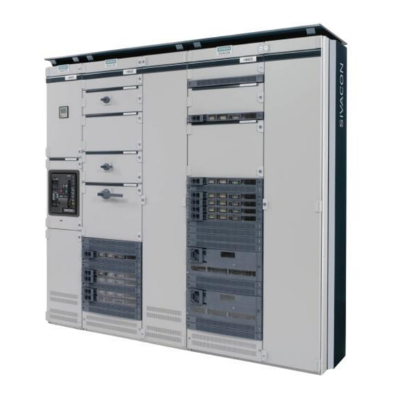
Siemens SIVACON S 8PQ Series Operating Instructions Manual - Page 8
Browse online or download pdf Operating Instructions Manual for Industrial Equipment Siemens SIVACON S 8PQ Series. Siemens SIVACON S 8PQ Series 40 pages. Design-verified low-voltage switchboard
Also for Siemens SIVACON S 8PQ Series: Operating Instructions Manual (11 pages)

- 1. Table of Contents
- 2. Sivacon Bauartgeprüfte Niederspannungsschaltanlage S8 - Felder mit Abzweigen in Einschubtechnik Design-Verified Low-Voltage Switchboard S8- Cubicles with Feeders in Withdrawable Design Betriebsanleitung / Operating Instructions Bestell-Nr. / Order No.: 8P
- 3. Description of the MCC Cubicle
- 4. Electrical Connections
1.2 Maximale Feldgewichte
Die Feldgewichte sind ohne horizontale Hauptsammelschiene und
ohne Einschübe.
1.3 Vertikale Feldschiene
1.3.1 Aufbau
L1 L2 L3 N
Für Einbauten in Festeinbau siehe Betriebsanleitung 8PQ9800-1AA50
1.3.2 Shutter und Abdeckungen für Feldschiene
Als Option kann für die Einschübe ein Shutter zum Verschluss der
Öffnungen für die Trennkontakte im Steckschienenkanal angeboten
werden. Der Shutter weist eine Zweipunkt-Verriegelung auf, das
heißt er kann nicht mit einer Hand geöffnet werden. Erst wenn der
Einschub in das entsprechende Fach eingesetzt wird, wird die Ver-
riegelung für den Shutter aufgehoben. Der Shutter wird erst geöffnet,
wenn der Einschub von der Trenn- in die Betriebsstellung gebracht
wird.
Der Shutter ist in den unteren 50mm des Faches angeordnet. Die
Öffnungen im Steckschienenkanal oberhalb des Shutters in diesem
Fach sind bei Ausführung mit Shutter mit dem gleichen Teil abge-
deckt, nur dass das Entfernen der oberen Fahnen an diesem Teil
entfällt. Für weitere Information siehe 4.4.2.1
Shutter Entriegelung
Shutter unlocking
Shutter geöffnet
Shutter open
Shutter open
6
1.3 Maximum cubicle weights
The cubicle weights are without horizontal main busbar and without
widthdrawable units.
Höhe
Feldbreite [mm]
Height
Cubicle width [mm]
[mm]
600
1000
2000
260kg
300kg
2200
280kg
320kg
1.3 Vertical distribution busbars
1.3.1 Design
Steckschienenkanal
Plug-in bus duct
Flach- oder Profilkupfer
Flat copper or profile bar
Öffnungen für Trennkontakte
Openings for contacts
For fixed mounted design, see Operation instructions 8PQ9800-
1AA50
1.3.2 Shutters and covers for distribution busbars
For the withdrawable units, an optional shutter can be supplied for
locking the openings for the contacts in the plug-in duct. The shutter
has a two-point locking, i.e. it cannot be opened with one hand. The
locking for the shutter is only released when the withdrawable unit is
placed into the appropriate compartment. The shutter is just opening
when the withdrawable unit is moved from the disconnected position
to the connected position.
The shutter is placed in the lower 50mm of the compartment. The
openings in the plug-in duct above the shutter in this compartment
are covered with the same part as the version with shutters. Only the
removing of the upper flags at this part does not apply. For further
information refer to 4.4.2.1
Shutter geschlossen
Shutter closed
Abdeckung Steckschienenka-
Shutter
nal (Option)
Shutter
Cover plug-in duct (optional)
Shutter
8PQ9800-3AA48
