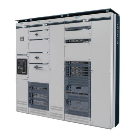
Siemens SIVACON S 8PQ Series Operating Instructions Manual - Page 10
Browse online or download pdf Operating Instructions Manual for Industrial Equipment Siemens SIVACON S 8PQ Series. Siemens SIVACON S 8PQ Series 11 pages. Design-verified low-voltage switchboard
Also for Siemens SIVACON S 8PQ Series: Operating Instructions Manual (40 pages)

4 Cuidado
Advertencia
En la utilización de aparatos eléctricos y tableros
de distribución, inevitablemente hay determinadas
piezas de estos que están sometidas a una tensión
peligrosa y pueden moverse con rapidez piezas
mecánicas, incluso maniobradas a distancia.
Si no se observan las disposiciones de seguridad e
indicaciones de precaución, pueden producirse
graves lesiones corporales o daños materiales.
Antes de realizar trabajos en la parte fija del tablero
de baja tensión, aislar de alimentación el tablero
(incluida la auxiliar), proteger contra reconexión,
asegurarse de que no hay tensión, poner a tierra y
cortocircuitar. Respetar todos los reglamentos e
instrucciones de seguridad de funcionamiento.
El cuidado se describe en el instructivo 8PQ9800-7AA73, capítulo 2.
Además deben observarse en las siguientes indicaciones 8PQ9800-
7AA80.
Para los aparatos incorporados, es obligatorio observar las
indicaciones que figuran en el instructivo del fabricante.
4.1 Inspección
El procedimiento de inspección se describe en el instructivo
8PQ9800-7AA73, capítulo 2.3. Para las unidades extraíbles con
convertidor de frecuencia deben realizarse además las siguientes
comprobaciones:
·
Inspección visual del convertidor de frecuencia
·
Inspección visual de los ventiladores de la unidad extraíble (y
limpieza en caso necesario)
4.2 Mantenimiento
El mantenimiento se describe en el instructivo 8PQ9800-7AA73,
capítulo 2.4. Eliminar el polvo y la suciedad acumulados.
4.3 Reparación
Los procedimientos de reparación se describen en el instructivo
8PQ9800-7AA73, capítulo 2.5. Además deben observarse las
siguientes indicaciones.
4.3.1 Sustitución de ventiladores
Cada una de las unidades extraíbles con convertidor de frecuencia
está provista de dos ventiladores de larga vida útil. Si falla uno de los
ventiladores, se emite un aviso de alarma. La unidad extraíble puede
seguir funcionando durante un tiempo limitado con un
ventilador. Sin embargo, el ventilador averiado debe sustituirse lo
antes posible:
·
Desconectar el interruptor principal
·
Extraer la unidad extraíble del compartimento
·
Soltar dos tornillos M4 (C) de la caja de ventiladores (D)
·
Inclinar ligeramente hacia delante la placa de montaje (E) con los
dos ventiladores y sacarlos de la caja de ventiladores hacia arriba
·
Desmontar el ventilador averiado (F) de la placa de montaje
·
Montar el ventilador nuevo y a continuación colocar de nuevo en
orden inverso la placa de montaje con los dos ventiladores
D
C
8
4 Maintenance
Warning
During operation of electrical equipment and
switchgear, certain parts are live and hazardous
voltages therefore present. Mechanical parts can
move very fast, even if remote controlled.
Non-observance of the safety instructions and
warnings can result in severe personal injury or
property damage.
Before working on the fixed-mounted part of the
low-voltage switchgear, isolate the switchgear
(including auxiliary supply), secure it against
reclosing, verify dead state, and earth and
shortcircuit it. Comply with all regulations and
relevant safety rules!
The maintenance is to be carried out accordingly to the operating
instruction 8PQ9800-7AA73, chapter 2. Additionally the following
notes in 8PQ9800-7AA80 have to be considered.
For the fitted supplies the specifications of the manufacturer's
operating manual are leading and to be considered accordingly.
4.1 Inspection
The maintenance is to be carried out accordingly to the operating
instruction 8PQ9800-7AA73, chapter 2.3. Additionally the following
checks are to carried out for withdrawable units with frequency
converters:
·
visual inspection of the frequency converter
·
visual inspection of the fan in the withdrawable unit (cleaning, if
necessary)
4.2 Preventive maintenance
The maintenance is to be carried out accordingly to the operating
instruction 8PQ9800-7AA73, chapter 2.4. Existing dust and dirt have
to be cleaned
4.3 Corrective maintenance
The corrective maintenance is to be carried out accordingly to the
operating instruction 8PQ9800-7AA73, chapter 2.5. Additionally the
following notes have to be considered.
4.3.1 Replacement fans
The withdrawable units with frequency converters are fitted with two
long life fans each. If one fan should fail, a warning signal occurs.
The withdrawable units can be operated further with one fan for a
solo
limited time period. However, the damaged fan should be replaced
as fast as possible:
·
Turn off the main switch
·
Remove the withdrawable unit from the compartment
·
Loosen the two M4 bolts (C) on the fan box (D)
·
Tilt the mounting plate (E) with the two fans slightly forward and
take it out of the fan box
·
Disassemble the damaged fan (F) from the mounting plate
·
Replace the new fan and insert the mounting plate with the two
fan in a reverse order
E
F
8PQ9800-7AA81
