Siemens 3NP42 7 Brochure - Page 25
Browse online or download pdf Brochure for Switch Siemens 3NP42 7. Siemens 3NP42 7 50 pages. Switch disconnectors and fuses
All switch disconnectors in IP00 degree of protection
Conductor connecting screws and fuse partitions are generally included in the scope of delivery
Rated
Fuse links
uninter-
to DIN 43620
rupted
Size
current
I
u
A
3-pole for LV HRC fuses
63
00 and
000
125
00 and
000
160
00 and
000
250
1 and 2
400
2 and 1
3KL52 30–1AB01
630
3 and 2
800
3 and 2
4-pole for LV HRC fuses
63
00 and
000
125
00 and
000
160
00 and
000
250
1 and 2
400
2 and 1
3KL52 40–1AB01
630
3 and 2
3-pole for fuses to BS 88
63
Form A2/A3
125
Form A2/A3
125
Form A4
160
Form A4
250
Form B1–B3
400
Form B1–B3
630
Form C1–C3
3KL52 30–1AJ01
800
Form C1–C3
4-pole for fuses to BS 88
63
Form A2/A3
125
Form A2/A3
125
Form A4
160
Form A4
250
Form B1–B3
400
Form B1–B3
630
Form C1–C3
3KL52 40–1AJ01
with fuses
Fuse monitoring through 5TT3 170 safety monitor with a floating
1S signal contact, see Catalog ET B1 "BETA Installation Equip-
ment".
1) Silver-plated fuse blade.
Silver-plated isolating links can be used if desired.
2) When using SITOR semiconductor protection fuse inserts, see page 7/29.
* This quantity or a multiple thereof can be ordered.
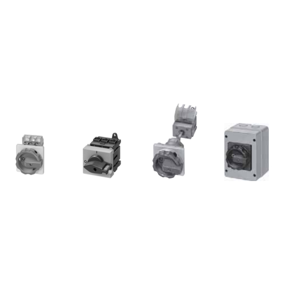
SENTRIC KL Switch Disconnectors with Fuses
1)
DT
Basic switch version
2)
without handle
Opera-
tional class
Order No.
}
gG, aM
3KL50 30–1AB01
}
gG, aM
3KL52 30–1AB01
}
gG, aM
3KL53 30–1AB01
}
gG, aM
3KL55 30–1AB01
}
gG, aM
3KL57 30–1AB01
gG, aM
X
3KL61 30–1AB0
gG, aM
D
3KL62 30–1AB02
gG, aM
B
3KL50 40–1AB01
gG, aM
B
3KL52 40–1AB01
gG, aM
B
3KL53 40–1AB01
gG, aM
B
3KL55 40–1AB01
gG, aM
B
3KL57 40–1AB01
gG, aM
A
3KL61 40–1AB00
B
3KL50 30–1AG01
B
3KL52 30–1AG01
B
3KL52 30–1AJ01
B
3KL53 30–1AJ01
B
3KL55 30–1AG01
B
3KL57 30–1AG01
A
3KL61 30–1AG00
D
3KL62 30–1AG00
B
3KL50 40–1AG01
B
3KL52 40–1AG01
B
3KL52 40–1AJ01
B
3KL53 40–1AJ01
B
3KL55 40–1AG01
B
3KL57 40–1AG01
C
3KL61 40–1AG00
Surface and flush mounting
PS*
Weight
DT
8UC6 EMERGENCY-
per PU
STOP door-coupling
approx.
rotary operating mech-
anism (red handle,
yellow indicator plate)
kg
Order No.
}
1 unit
1.050
8UC61 21–3BB10
}
1 unit
1.980
8UC62 22–3BB20
}
1 unit
2.200
8UC62 22–3BB20
}
1 unit
5.710
8UC63 23–3BB30
}
1 unit
5.400
8UC63 23–3BB30
}
1 unit 17.600
8UC64 24–3BB44
}
+8UC92 53
}
1 unit 15.200
8UC64 24–3BB44
}
+8UC92 53
}
1 unit
2.210
8UC62 22–3BB20
}
1 unit
2.190
8UC62 22–3BB20
}
1 unit
2.340
8UC62 22–3BB20
}
1 unit
5.570
8UC63 23–3BB30
}
1 unit
5.670
8UC63 23–3BB30
}
1 unit 15.400
8UC64 24–3BB44
}
+8UC92 53
}
1 unit
0.993
8UC61 21–3BB10
}
1 unit
1.930
8UC62 22–3BB20
}
1 unit
2.030
8UC62 22–3BB20
}
1 unit
2.170
8UC62 22–3BB20
}
1 unit
5.140
8UC63 23–3BB30
}
1 unit
5.660
8UC63 23–3BB30
}
1 unit 15.000
8UC64 24–3BB44
}
+8UC92 53
}
1 unit 14.200
8UC64 24–3BB44
}
+8UC92 53
}
1 unit
2.140
8UC62 22–3BB20
}
1 unit
2.160
8UC62 22–3BB20
}
1 unit
2.120
8UC62 22–3BB20
}
1 unit
2.230
8UC62 22–3BB20
}
1 unit
5.660
8UC63 23–3BB30
}
1 unit
6.440
8UC63 23–3BB30
}
1 unit 15.700
8UC64 24–3BB44
}
+8UC92 53
Siemens LV 10 · 2004
PS*
Weight
per PU
approx.
kg
1 unit
0.353
1 unit
0.426
1 unit
0.426
1 unit
0.999
1 unit
0.999
1 unit
1.180
1 unit
0,115
1 unit
1.180
1 unit
0.115
1 unit
0.426
7
1 unit
0.426
1 unit
0.426
1 unit
0.999
1 unit
0.999
1 unit
1.180
1 unit
0.115
1 unit
0.353
1 unit
0.426
1 unit
0.426
1 unit
0.426
1 unit
0.999
1 unit
0.999
1 unit
1.180
1 unit
0.115
1 unit
1.180
1 unit
0.115
1 unit
0.426
1 unit
0.426
1 unit
0.426
1 unit
0.426
1 unit
0.999
1 unit
0.999
1 unit
1.180
1 unit
0.115
7/25