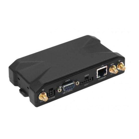
Actsoft LMU-5000 Hardware And Installation Manual - Page 5
Browse online or download pdf Hardware And Installation Manual for GPS Actsoft LMU-5000. Actsoft LMU-5000 8 pages.

I/O Connector
The LMU-5000™'s features expanded I/O capabilities via its 22-Pin Molex 43045-2202
connector. Its pin-out is as follows:
Signal
Pin
Name
1
Input 1
2
Input 2
3
Input 3
4
Input 4
5
Input 5
6
Input 6
7
Input 7
8
1BB T Data
9
1BB GND
10
1 BB R Data
11
1 BB Gnd
12
Output 0
13
Output 1
14
Output 2
15
Output 3
16
Output 4
Output 5 -
17
LED
Output 6 -
18
LED
19
ADC 2
20
ADC 3
21
ADC 4
22
ADC 5
Description
Input 1 – Digital Input
Input 2 – Digital Input
Input 3 – Digital Input
Input 4 – Digital Input
Input 5 – Digital Input
Input 6 – Digital Input
Input 7 – Digital Input
1 Bit Bus Data (T)
1 Bit Bus Ground
1 Bit Bus Data (R)
1 Bit Bus Ground
Output 0 - Starter
Disable Relay Driver
Output 1 - Digital Output
Output 2 - Digital Output
Output 3 - Digital Output
Output 4 - Digital Output
Output 5 - LED 1 Driver
Output 6 - LED 2 Driver Orange & Green
Analog to Digital Input 2
Analog to Digital Input 3
Analog to Digital Input 4 Orange & Red
Analog to Digital Input 5
5C889
Input or
Color
Output
Blue
Input
Orange
Input
Violet
Input
Gray
Input
Green & White
Input
Blue & White
Input
Black & White
Input
Green & Black
Input/Output
Black
Ground
Orange & Black
Input/Output
Black
Ground
Green
Output
Brown
Output
Yellow
Output
Blue & White &
Output
Orange
Green & Black
Output
& Orange
Red & Green
Output
Output
Black & Red
Input
White & Red
Input
Input
Blue & Red
Input
