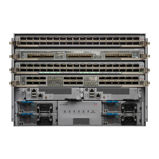
Cisco NCS 5500 Series Manual - Page 15
Browse online or download pdf Manual for Network Router Cisco NCS 5500 Series. Cisco NCS 5500 Series 25 pages. Connect router to the network
Also for Cisco NCS 5500 Series: Configuration Manual (19 pages), Connection Manual (24 pages)

Connect Router to the Network
1
2
Required Tools and Equipment
You need these tools to install the 40-Gigabit QSFP+ / 100-Gigabit QSFP28 transceiver modules:
• Wrist strap or other personal grounding device to prevent ESD occurrences.
• Antistatic mat or antistatic foam to set the transceiver on.
• Fiber-optic end-face cleaning tools and inspection equipment.
For information on inspecting and cleaning fiber-optic connections, see
Cables.
Installing the 40-Gigabit QSFP+ or 100-Gigabit Transceiver Module
The QSFP+ or QSFP28 transceiver module can have either a bail-clasp latch or a pull-tab latch. Installation
procedures for both types of latches are provided.
Caution
The QSFP+ or QSFP28 transceiver module is a static-sensitive device. Always use an ESD wrist strap or
similar individual grounding device when handling QSFP+ or QSFP28 transceiver modules or coming into
contact with system modules.
To install an QSFP+ or QSFP28 transceiver module, follow these steps:
Step 1
Attach an ESD wrist strap to yourself and a properly grounded point on the chassis or the rack.
Step 2
Remove the QSFP+ or QSFP28 transceiver module from its protective packaging.
Step 3
Check the label on the QSFP+ or QSFP28 transceiver module body to verify that you have the correct model for your
network.
Step 4
For optical QSFP+ or QSFP28 transceiver modules, remove the optical bore dust plug and set it aside.
Step 5
For QSFP+ or QSFP28 transceiver modules equipped with a pull-tab, hold the transceiver so that the identifier label is
on the top.
Step 6
For QSFP+ or QSFP28 transceiver modules equipped with a bail-clasp latch, keep the bail-clasp aligned in a vertical
position.
Step 7
Align the QSFP+ or QSFP28 transceiver module in front of the module's transceiver socket opening and carefully slide
the QSFP+ or QSFP28 transceiver into the socket until the transceiver makes contact with the socket electrical connector
(see the figure below).
40GBASE QSFP+
3
transceiver body
Bail-clasp latch
Required Tools and Equipment
Electrical connection to
the module circuitry
Maintain Transceivers and Optical
Connect Router to the Network
15
