CAB 3014 L/R 2100 Assembly Instructions Manual - Page 8
Browse online or download pdf Assembly Instructions Manual for Industrial Equipment CAB 3014 L/R 2100. CAB 3014 L/R 2100 13 pages. Front-side applicator

3
Mounting
8
3.1
Mounting the applicator parts on the printer
Fig. 3
Mounting Applicator - Printer
i
Note!
In case of order a complete / configured system will be mounted some parts.
Several steps of mounting dropped. Particularly pad and product sensor.
1. Hang on the control assembly (8) with the female part of hinges (2) at the printer mounted hinges (3).
2. Connect SUB-D 15 male connector (7) to the female connector (6) of the printer.
3. To secure the applicator against slipping out out of hinges loosen screw (5) and move metal part (4) under the
hinges and tighten screw (5).
4. Swing the applicator to the printer and tighten the thumbscrew (1).
5. Set the base plate with swing cylinder.(11) on the bottom side of the printer (9). The holes on the base plate must
be over the holes in the printer chassis. Tighten the screws (12) to mount the base plate (1) on the printer (9).
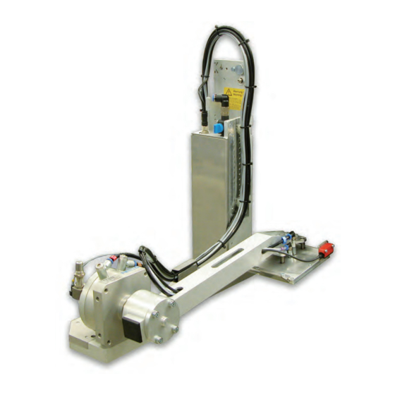
6. Mount the pad (17) with the screws (part of the pad assembly) on the swing lever (18) of the applicator.
7. Mount the sensor bracket (16) with screws (13) on pad (17) .
8. Mount product sensor (14) with screws (15) M3x16 on the the sensor bracket (16).
9. Mount blow tube(10) . next chapter
1
2
3
4
5
6
3
7
8
2
3
18
8
9
8
10
11
12
13
14
15
16
17
