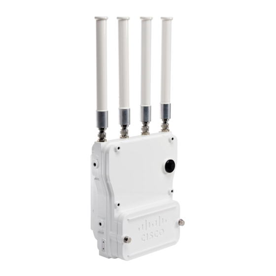
Cisco Catalyst IW6300H-DC Installing Manual - Page 21
Browse online or download pdf Installing Manual for Wireless Access Point Cisco Catalyst IW6300H-DC. Cisco Catalyst IW6300H-DC 28 pages.

Installing the Access Point
Note
The marked DC input range is an absolute range. Do not apply tolerances.
Note
In all cases above, the AC branch circuit powering the access point must be limited to no more than 20A from
the over-protection device supplied by the user. This branch power protection must meet all local and national
electrical codes.
The IW6300 access point for hazardous locations can be connected to more than one power source. The access
point detects the available power sources and switches to the preferred power source using the following
priority:
1. AC or DC power
2. Power over Ethernet
Connecting a Power Injector
The power injector provides 55 VDC to the access point over the Ethernet cable and supports a total end-to-end
Ethernet cable length of 100 m (328 ft) from the switch to the access point.
Caution
Power injector AIR-PWRINJ-60RGDx= is not certified for installation within hazardous locations environments.
Note
The PoE Out power is disabled when the access point is powered by the power injector. But the PoE Out data
link can still be active when using power injector.
When your access point is powered by an optional power injector, follow these steps to complete the installation:
Procedure
Step 1
Before applying PoE to the access point, ensure that the access point is grounded (see
Point , on page
Step 2
Connect a CAT5e or better Ethernet cable from your wired LAN network to the power injector.
Danger
Use only the power injector (AIR-PWRINJ-60RGDx=) for the access point.
• IW-6300H-AC-x-K9: 85-264V~ maximum, marked 100-240V~, 50-60Hz, 1.3A
• IW-6300H-DC-x–K9: 44 to 57Vdc, 1.2A
• IW-6300H-DCW-x-K9: 10.8 to 36Vdc, 5.9A
19).
To reduce the risk of fire, use only No. 26 AWG or larger telecommunication line cord. Statement
1023
Connecting a Power Injector
Grounding the Access
Installing the Access Point
21
