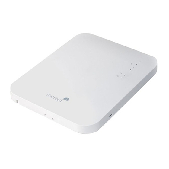
Cisco Meraki MR32 Installation Manual - Page 12
Browse online or download pdf Installation Manual for Wireless Access Point Cisco Meraki MR32. Cisco Meraki MR32 16 pages.

Tip: Pre-assemble rubber spacers and screws to the mount cradle. The mount cradle can then be held with one hand
while the other hand holds a screwdriver. If mounting your MR18 to a dropped ceiling, skip to the "Power the MR18"
section.
Electrical Junction Box Mount Using mount cradle
The MR18 can be mounted to a 4" square cable junction box, a 3.5 or 4" round cable junction box, or various U.S. and
European outlet boxes (mounting screws are not included).
Using appropriate mounting hardware for your specific type of junction box, attach the mount cradle to the junction box.
Plenum Mount (Above Drop Ceiling)
The MR18 can be mounted to the T-bar grid above the tiles of a drop ceiling using a 3rd party T-bar box hanger (not
included). The Erico Caddy 512A is recommended and is used in installation instruction illustrations. Note: a
UL2043-rated Ethernet cable should be used for a plenum installation.
1. Adjust the height of the T-bar box hanger crossbar to make sure there is adequate clearance between the access
point and the top of the ceiling tiles. Tighten the height adjusting screws.
2. Attach the bracket mounting clip (included with T-bar box hanger) to the center of the T-bar box hanger crossbar.
3. Attach the MR18 mount cradle to the access point mounting bracket using a 6-32 screw, washer, and nut (not
included with T-bar box hanger) and the Above Drop Ceiling (Box Hanger) hole in the mount cradle (reference
Mounting Template).
4. Securely attach the clips on either side of the T-bar box hanger to the suspended ceiling grid T-rails.
5. Connect a grounding wire (not included with T-bar box hanger) to the grounding hole in the bracket mounting clip
and to metal building structure. A grounding wire is required to comply with the U.S. National Electric Safety Code.
Power the MR18
If mounting to an electrical junction box, feed the Ethernet cable through the cable access hole in the mount cradle. If
mounting to a wall or ceiling, the Ethernet cable will feed from behind the MR18.
Powering the MR18 with the Meraki AC Adapter (sold separately)
1. Plug the power cord into the MR18 and the other end into a wall outlet.
2. Plug an Ethernet cable that is connected to an active Ethernet connection into the Eth0 port on the MR18.
Powering the MR18 with the Meraki 802.3af Power over Ethernet Injector (sold separately)
1. Plug the power cord into the PoE Injector and the other end into wall power.
2. Plug an Ethernet cable that is connected to an active Ethernet connection into the "IN" port on the injector.
3. Route Ethernet cable from the "OUT" port on the injector to the Eth0 port in the cable bay of the MR18.
Powering the MR18 with an 802.3af Power over Ethernet Switch
Route Ethernet cable from a port on an active 802.3af PoE switch to the Eth0 port in the bay of the MR18. The MR18 is
Gigabit Ethernet-capable. To maximize device performance, a Gigabit-capable switch should be used.
12
