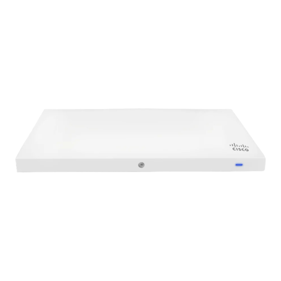
Cisco Meraki MR33s Installation Manual - Page 10
Browse online or download pdf Installation Manual for Wireless Access Point Cisco Meraki MR33s. Cisco Meraki MR33s 13 pages.

the MR33" section.
Electrical Junction Box Mount Using mount cradle
The MR33 can be mounted to a 4" square cable junction box, a 3.5 or 4" round cable junction box, or various U.S.
and European outlet boxes (mounting screws are not included).
Using appropriate mounting hardware for your specific type of junction box, attach the mount cradle to the
junction box.
Power the MR33
If mounting to an electrical junction box, feed the Ethernet cable through the cable access hole in the mount cradle. If
mounting to a wall or ceiling, the Ethernet cable will feed from behind the MR33. The
this document lists the different powering options and their unique characteristics.
Mount the MR33
Attach the MR33 to the Mount Cradle
(This section applies to wall and/or solid ceiling, drop ceiling or electrical junction box mount
where you have already installed the mount cradle.)
The MR33 attaches to the mount cradle with two tabs on the cradle that insert into the MR33, and is secured to the
cradle using one screw.
To attach the MR33 to the mount cradle properly, line up the top edge of the AP with the top tab of the mount cradle.
Since the cradle is already mounted to the wall, guide the MR33 towards the top tab and insert the top tab into the
MR33's slot.
Then adjust the MR33 to guide the MR33's bottom slot into the cradle's bottom tab until it clicks into place. Once in
place, the MR33 should be secured to the cradle by using one of the included screws in the cradle's bottom tab.
"Power Source
Options" section of
10
