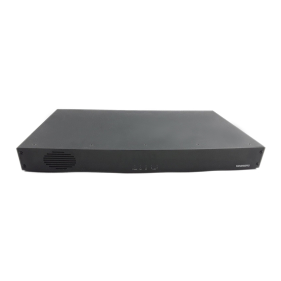
Cisco TelePresence System Codec 3000 MXP The Physical Interface Manual - Page 15
Browse online or download pdf The Physical Interface Manual for Conference System Cisco TelePresence System Codec 3000 MXP. Cisco TelePresence System Codec 3000 MXP 28 pages.

MXP Series Codecs
Contents
Data Ports
Data port 1
Pin
Signal
Direction
name
1
Carrier
From DCE
detect, CD
2
Receive data,
From DCE
RXD
3
Transmit
To DCE
data, TXD
4
1
Data terminal
From DCE
ready, DTR
5
Signal GND
6
Data set
From DCE
ready, DSR
7
Ready to
To DCE
send, RTS
8
Clear to
From DCE
send, CTS
9
Ring
From DCE
indicator, RI
1) The Cisco main camera is normally connected to data port 2 and pin No.
4 provides 12 Vdc / 1 A to the main camera. Otherwise the pin-outs are the
same for the two data ports.
D14790.01 MXP Series Codec Physical Interface Guide, May 2011.
© 2011 Cisco Systems, Inc. All rights reserved.
Introduction
Data Ports
Data port 2
Signal
Direction
name
Carrier
From DCE
detect, CD
Receive data,
From DCE
RXD
Transmit
To DCE
data, TXD
12 V / 1 A
Signal GND
Data set
From DCE
ready, DSR
Ready to
To DCE
send, RTS
Clear to
From DCE
send, CTS
Ring
From DCE
indicator, RI
Codec 6000 MXP
Codec 6000 MXP
USB
interface.
For future
use.
15
Physical interface guide
Codec 3000 MXP
Data port 1 (upper) and 2 (lower). The Data
ports are implemented as Digital Circuit
Terminating Equipment (DCE).
NOTE!
The Cisco main camera is normally
connected to data port 2 and pin No. 4
provides 12 Vdc / 1 A to the main camera.
Otherwise the pin-outs are the same for the
two data ports.
9-pin D-sub pin-out
External view of socket
5
1
9
6
Contact us
www.cisco.com
