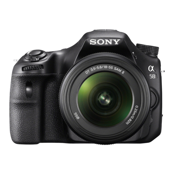
Sony SLT-A58Y Service Manual - Page 22
Browse online or download pdf Service Manual for Digital Camera Sony SLT-A58Y. Sony SLT-A58Y 26 pages. Interchangeable lens digital camera

2-1-11. MIRROR BOX SECTION (SUB UNIT-2)
ns: not supplied
ns
ns
501
#241
ns
511
(including M903 (charge motor) and
SLK-009 flexible complete board)
Ref. No.
Part No.
Description
501
X-2582-300-1
MB FRONT FRAME ASSY
502
4-292-464-01
MB MIRROR FRAME HOLDING SP
503
A-1837-335-A
MB MIRROR FRAME HOLDER ASSY (Note 1)
504
A-1855-640-A
P.O.I (SERVICE) (Note 1, 2)
505
4-194-447-01
MB LEVER CUSHION
506
4-292-475-01
MB SHUTTER CHARGE LEVER
507
4-292-476-01
MB SHUTTER CHARGE LEVER SP
508
4-292-473-01
MB DECELERATION GEAR 1
509
4-292-474-01
MB DECELERATION GEAR 2
SLT-A58K/A58M/A58Y_L2
502
503
(Note 1)
504
(Note 1, 2)
506
505
507
#23
510
#23
508
509
#23
Ref. No.
Part No.
Description
510
X-2582-303-1
MB SHUTTER CHARGE CAMGEAR ASSY
511
A-1837-338-A
SLK FPC UNIT 870 BOARD, COMPLETE
(including M903 (charge motor) and SLK-009 flexible
512
4-292-574-01
MB LENS LOCK BASE PLATE
513
4-292-585-01
MB AF/MF SELECTION LEVER
#23
3-080-204-11
SCREW, TAPPING, P2
#241
3-703-816-46
SCREW (M1.4X2.5), SPECIAL HEAD
Screw
#23: M1.7 X 4.0 (Tapping)
(Black)
3-080-204-11
1.7
4.0
Note
Note 1: If the MB Mirror Frame Holder Assy (P.O.I.) is raised and
then pushed from the front side with the Shutter Unit (AFE-
3032) and the AS Slider Unit (863) have been removed, it
may drop off behind and get scratched or damaged.
Note 2: Refer to "1-1. METHOD FOR REPLACING THE P.O.I." on
page 1-1 when replacing the P.O.I. without disassembling
the camera.
#23
512
513
complete board)
2-13
#241: M1.4 X 2.5
(Black)
3-703-816-46
1.4
2.5
