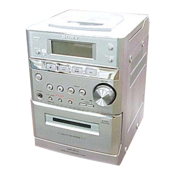
Sony SS-CEP515 Service Manual - Page 4
Browse online or download pdf Service Manual for Stereo System Sony SS-CEP515. Sony SS-CEP515 46 pages.

HCD-EP515
Ver 1.2 2003. 07
Tuner section
FM stereo, FM/AM superheterodyne tuner
FM tuner section
Tuning range
87.5 - 108.0 MHz (50-kHz
step)
Antenna
FM lead antenna
Antenna terminals
75 ohms balanced
Intermediate frequency
10.7 MHz
AM tuner section
Tuning range
Pan-American model:
530 - 1,710 kHz
(with the tuning interval
set at 10 kHz)
531 - 1,602 kHz
(with the tuning interval
set at 9 kHz)
European model:
531 - 1,602 kHz
(with the tuning interval
set at 9 kHz)
Other models:
530
- 1,710 kHz
(with the tuning interval
set at 10 kHz)
531 - 1,602 kHz
(with the tuning interval
set at 9 kHz)
Antenna
AM loop antenna, external
antenna terminal
Intermediate frequency
450 kHz
General
Power requirements
North American model:
120 V AC, 60 Hz
European model:
230 V AC, 50/60 Hz
Other models:
230 V AC, 50/60 Hz
Power consumption
North American model:
50 watts
European model:
50 watts
0.3 watts (in the standby
mode)
Other models:
50 watts
Approx. 163 × 233 × 237
Dimensions (w/h/d)
mm
Mass
Approx. 3.6 kg
Supplied accessories
Remote (1)
R6 (size AA) batteries (2)
AM loop antenna (1)
FM lead antenna (1)
Design and specifications are subject to change
without notice.
2
TABLE OF CONTENTS
·········································································· 5
3-1. Rear Cabinet ··································································· 7
3-2. CD Cabinet Section, Front Panel Section ······················· 8
3-3. CD Mechanism Deck (KSM-213EDP) ··························· 8
3-4. CONTROL Board, BACK LIGHT Board ······················ 9
3-5. Tape Mechanism Deck (CMAL1Z240A) ······················· 9
3-6. Cassette Door Assy ······················································· 10
3-7. POWER Board, MAIN Board ······································ 10
3-8. Optical Pick-up (KSS-213E/C2N) ································ 11
······································································ 15
6-1. Block Diagram - CD Section - ··································· 17
6-2. Block Diagram - Main Section - ································ 18
6-3. Printed Wiring Board - CD Section - ························· 19
6-4. Schematic Diagram - CD Section - ···························· 20
6-5. Printed Wiring Borads - Main Section - ····················· 21
6-6. Schematic Diagram - Main Section - ························· 22
6-7. Printed Wiring Board - Control Section - ··················· 23
6-8. Schematic Diagram - Control Section - ······················ 24
6-9. Printed Wiring Board - Power Section - ····················· 25
6-10. Schematic Diagram - Power Section - ······················ 25
6-11. IC Pin Function Description ······································· 28
7-1. Cabinet Section ····························································· 30
7-2. Front Panel Section ······················································· 31
7-3. CD Cabinet Section ······················································ 32
7-4. Optical Pick-up Block (KSM-213EDP) ······················· 33
······················································· 3
····························· 12
······························· 13
······································· 34
