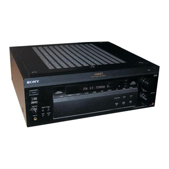
Sony STR-DA80ES - Fm Stereo / Fm-am Receiver Operating Instructions Manual - Page 9
Browse online or download pdf Operating Instructions Manual for Stereo System Sony STR-DA80ES - Fm Stereo / Fm-am Receiver. Sony STR-DA80ES - Fm Stereo / Fm-am Receiver 40 pages. Limited warranty (es products)
Also for Sony STR-DA80ES - Fm Stereo / Fm-am Receiver: Operating Instructions Manual (39 pages), Technical Background (38 pages), Limited Warranty (1 pages)

Selecting the impedance
Set the IMPEDANCE SELECTOR for the front speakers
as indicated in the table below. Check the instruction
manual of your speakers if you're not sure of the
impedance. (This information is usually printed on a
label on the back of the speaker.)
If nominal impedance of
Set IMPEDANCE SELECTOR to
your speaker is
Between 4 and 8 ohms
8 ohms or higher
Selecting the speaker system
If you connect only one set of front speakers, set the
SPEAKERS selector on the front panel to A. If you
connect two sets of front speakers, see the following:
To drive
Set SPEAKERS selector to
Speaker system A (connected
to the FRONT SPEAKERS A
terminals)
Speaker system B (connected
to the FRONT SPEAKERS B
terminals)
Both speaker systems A and B
(parallel connection)
z
To connect any speaker pair through an amplifier
Connect the amplifier to the PRE OUT jacks of the
receiver to output the PRE OUT jack signals from the
amplifier's speaker terminals.
The signals output from the PRE OUT jacks are identical
to those output from the speaker terminals of the
receiver.
You can then connect any pair of speakers (e.g., the
front speakers) to the amplifier's speaker terminals.
TV/VCR Hookups
Overview
This section describes how to connect video
components to the receiver.
For digital connections, see "Digital Component
Hookups" on page 10.
TV/DBS
4 Ω
8 Ω
AC-3 RF IN
COAXIAL IN
OPTICAL IN
OPTICAL IN
OPTICAL IN
OPTICAL IN
OPTICAL OUT
DIGITAL
*
TV/DBS: USA, Canadian, and Australian models
TV: other models
A
What cables will I need?
• Audio/video cable (not supplied) (1 for each TV or LD
B
player; 2 for each VCR)
Yellow
White (L)
A+B
Red (R)
• Video cable (not supplied) (1 for a TV monitor)
z
If you want to watch high quality video images
You can use an S-VIDEO cable for the TV/DBS, LD,
VIDEO 1/2/3, and MONITOR jacks.
Note
The signal input from the S VIDEO IN jack is not output to
the normal VIDEO OUT jack. Nor is the signal input from
the VIDEO IN jack output to the S VIDEO OUT jack.
Hookups
The arrow
TV or Digital Broadcasting System (DBS) tuner
DBS tuners can be used with the USA, Canadian, and
Australian models.
Getting Started
Getting Started
*
VIDEO 2
MONITOR
ANTENNA
TV / DBS
LD / DVD
VIDEO 2
VIDEO 1
MONITOR
S-LINK
S VIDEO
S VIDEO
S VIDEO
S VIDEO
S VIDEO
S VIDEO
S VIDEO
LD
IN
IN
OUT
IN
OUT
IN
OUT
CTRL A1
DVD
IN
LD
DVD
FM
VIDEO
VIDEO
VIDEO
VIDEO
VIDEO
VIDEO
OUT
IMPEDANCE
75Ω
IN
IN
OUT
IN
OUT
IN
SELECTOR
COAXIAL
LD
DVD
4 Ω
8 Ω
AM
AUDIO
AUDIO
AUDIO
AUDIO
AUDIO
AUDIO
TV
IN
IN
OUT
IN
OUT
IN
DBS
L
y
CD
R
DAT
MD
PRE OUT
PHONO
CD
DAT / MD
TAPE
y
FRONT
REAR
CENTER
DAT
L
L
L
MD
SIGNAL
WOOFER
GND
R
R
R
IN
IN
REC OUT
IN
REC OUT
IN
LD/DVD
VIDEO 1
Yellow
ç
indicates signal flow.
Receiver
TV / DBS
S VIDEO
IN
TV or DBS tuner
VIDEO
IN
AUDIO
IN
Ç
L
R
FRONT SPEAKERS
IMPEDANCE USE 4–16 Ω
R
B
L
R
A
L
AC OUTLET
+
+
AC 120V 60Hz
SWITCHED 120W / 1A MAX
–
–
CENTER SPEAKER
REAR SPEAKERS
R
L
+
+
–
–
IMPEDANCE USE 4–16 Ω
IMPEDANCE USE 4–16 Ω
Yellow
White (L)
Red (R)
Yellow
OUTPUT
VIDEO
AUDIO
L
R
(Continued)
9
