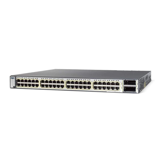
Cisco Catalyst 3750-E Series Getting Started Manual - Page 15
Browse online or download pdf Getting Started Manual for Network Hardware Cisco Catalyst 3750-E Series. Cisco Catalyst 3750-E Series 27 pages. Switches and power supply modules
Also for Cisco Catalyst 3750-E Series: Getting Started Manual (33 pages), Product Support Bulletin (6 pages), Product Support Bulletin (5 pages), Product Support Bulletin (6 pages), Installation Notes (20 pages)

• Temperature around the unit does not exceed 113°F (45°C). If the switch is installed in a closed
or multirack assembly, the temperature around it might be greater than normal room temperature.
• For copper connections on Ethernet ports, cable lengths from the switch to connected devices can
be up to 328 feet (100 meters).
• For cable lengths for X2 transceiver modules and SFP-module connections, see the hardware
installation guide on Cisco.com and the documentation that shipped with the module.
Installation Warning Statements
This section includes the basic installation warning statements. Translations of these warning
statements appear in the Regulatory Compliance and Safety Information for the Catalyst 3750-E and
Catalyst 3560-E Switch guide.
Warning
To prevent the switch from overheating, do not operate it in an area that exceeds the
maximum recommended ambient temperature of 113°F (45°C). To prevent airflow
restriction, allow at least 3 inches (7.6 cm) of clearance around the ventilation openings.
Statement 17B
Warning
Do not reach into a vacant slot or chassis while you install or remove a module or a fan.
Exposed circuitry could constitute an energy hazard. Statement 206
Warning
To prevent bodily injury when mounting or servicing this unit in a rack, you must take
special precautions to ensure that the system remains stable. The following guidelines
are provided to ensure your safety:
•
This unit should be mounted at the bottom of the rack if it is the only unit in the rack.
•
When mounting this unit in a partially filled rack, load the rack from the bottom to the top with
the heaviest component at the bottom of the rack.
•
If the rack is provided with stabilizing devices, install the stabilizers before mounting or
servicing the unit in the rack.
Statement 1006
15
