Digitrax DS78V Instructions Manual - Page 3
Browse online or download pdf Instructions Manual for Control Systems Digitrax DS78V. Digitrax DS78V 8 pages. Eight servo loconet stationary/accessory decoder for turnout control.

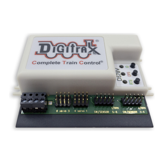
2.0 Setup DS78V Servo angle Adjustment mode:
The DS78V can be configured to conveniently drive all 8 servo outputs to the; T/
CW, Center or C/CCW servo angle positions for testing and installation.
1.
To go to Thrown/CW position: double click the RTS button with two quick
presses and releases in less than 1 second. All servo arms will go to the T/CW
position, and just the Green RTS led will blink rapidly. To exit from adjust-
ing back to normal operation, double click the RTS button again.
2.
To go to servo Center position: double click the OPS button with two quick
presses and releases in less than 1 second. All servos will go to the center
position, and just the Red OPS led will blink rapidly. To exit from adjusting,
double click the OPS button again.
3.
To go to Closed/CCW position: double click the ID button with two quick
presses and releases in less than 1 second. All servos will go to the C/CCW
position, and just the Green ID led will blink rapidly. To exit from adjusting,
double click the ID button again.
4.
You can enter Adjustment mode with just the 12V power hooked up, and do
not need a command station, active LocoNet or a throttle to do these servo
position adjustments.
3.0 Setup DS78V Ez-Routes:
The DS78V has 16 internal Routes with up to 8 SW# and T/C direction Entries
each. These can be set up by Ez-Routes method using the RTS button and switch
commands sent from a LocoNet throttle, connected PC or DCC track.
1.
Press and hold the RTS button for about 3 seconds and the ID and OPSW
LEDs will blink alternately to show one Route can be set up. Release the
RTS button.
2.
Select a switch address on your throttle between 1 and 16 and issue the
command direction for Closed. This will now be the Route Number you are
going to setup. Any previous Entries in this Route will now be replaced in
following steps.
3.
Select the desired TOP Switch address between 1 and 2000 and issue a C or
T direction command. This SW# and direction is that which will trigger this
Route to be executed when seen by this DS78V
4.
Now enter up to 7 more SW# and direction T or C for the other route Entries
required. The route entry ID/OPS LED will stop blinking indicating route is
full/completed.
5.
If you issue a SW# and direction twice consecutively that will also end route
entry.
6.
If this DS78V does not have a LocoNet connection but operates from DCC
Track power on the TKA/B terminals, then it will ignore Route Entries that
do not fall within the DS78V's Base address and next 7 servos.
7.
Best practice is to set TOP SW#'s in each route in a unique "phantom" switch
range e.g. 500 and above that do not control a physical switch. This will iden-
tify the issued switch is specifically a TOP or Route-start SW#.
8.
Ez-Routes do not have the ability to; read back , review or edit DS78V routes
already set up. For more powerful color graphics for comprehensive DS78V
Route review and editing consider using a DT602 as noted in section 6.0
9.
The green RTS LED will be steady ON if there are any routes programmed.
© 2021 Digitrax, Inc.
— 3 —
www.digitrax.com
