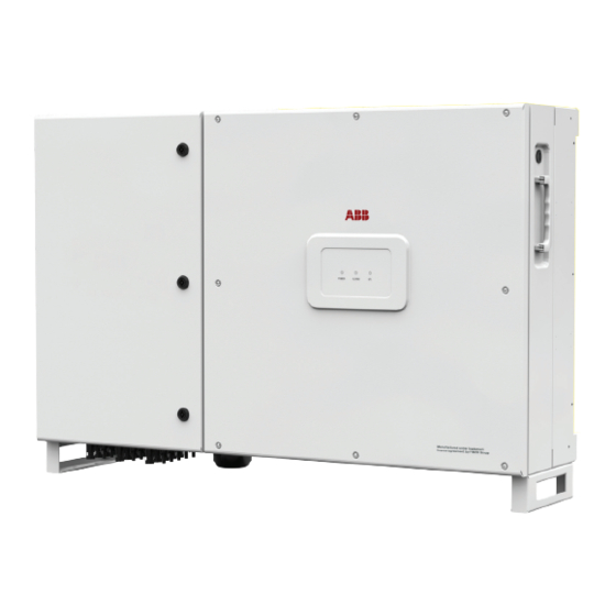
Fimer PVS-60-TL Quick Installation Manual - Page 3
Browse online or download pdf Quick Installation Manual for Industrial Equipment Fimer PVS-60-TL. Fimer PVS-60-TL 8 pages. Solar inverter

3. Inverter models and components
The inverter model should be chosen by a specialized technician who has a good knowledge of the installation conditions, the devices that will be installed
externally, and whether it will eventually be integrated into an existing system.
The following models of inverter are available:
Inverter model
Input channel
PVS-50(60)-TL
1
PVS-50(60)-TL-SX
3 (1 if paralleled) Yes
PVS-50(60)-TL-SX2 3 (1 if paralleled) Yes
Main components
01
Bracket
02
Locking brackets
03
Inverter/bracket anchor points
04
Wiring box front door
05
LED panel
06
Display
07
Keypad
08
Keylock
09
Lifting ring
10
Wi-Fi antenna connector
11
Locking brakets attachment point
12
Ethernet cable gland
13
Service cable gland
14
Handle
15
DC disconnect switch
16
Protective earth terminal (external) 39 DC input screw terminal block
17
DC cable glands
18
AC cable gland
Inverter (external view)
11
10
09
09
05
06 07
08
12
13
14
OFF
15
16
11
PVS-50/60-TL
24
17
INPUT
DC
OUTPUT AC
18
PVS-50/60-TL-SX / PVS-50/60-TL-SX2
INPUT
INPUT
DC
DC
19
1A
2A
3A
OUTPUT AC
1B
2B
3B
1C
2C
3C
1D
2D
3D
1E
2E
3E
20
21
18
PVS-50-TL
PVS-60-TL
30
30
36
31
31
41
40
32
32
37
39
33
38
35
READ THE MANUAL –
E
The illustration shows the main components and connections available on the communication and control board (30). Each connection cable reaches
the communication board through service cable glands (13) and Ethernet cable gland (12) .
DC switch DC SPD DC connection
No
Class 2 screw terminal blocks
Class 2 15 pairs quick fit connectorsPositive
Class 2 15 pairs quick fit connectorsPositive and negative Class 2
19 Input quick fit connectors ( channel 1)
20 Input quick fit connectors ( channel 2)
21 Input quick fit connectors ( channel 3)
22 Anti-condensation valve
23 Cooling section
24 Lower support
30 Communication and control board
31 Grounding kit (optional kit)
32 DC overvoltage surge arresters
33 DC disconnect switch
34 Negative (-) side string fuses
35 Positive (+) side string fuses
36 AC overvoltage surge arresters
37 Protective earth terminal (internal)
38 AC output screw terminal block
40 AC filter board
41 Parallel MPPT connection points
05
09
11
14
PVS-60
11
24
22
23
22
23
PVS-50-TL-SX
PVS-50-TL-SX2
PVS-60-TL-SX
PVS-60-TL-SX2
30
36
31
41
40
32
37
33
38
34
35
See the manual for details on the connections and functions available on the communication and control board.
String fuses
No
50 Parallel MPPT connection points
51 ALARM (multifunction relay) terminal block
52 AUX (multifunction relay) terminal block
53 RS485-1 and RS485-2 lines, R1ON/OFF and R2ON/OFF
(remote ON/OFF) and 5V auxiliary lines terminal block
54 RS485-1 line 120Ohm termination resistor switch
55 RS485-1 communication card housing
56 RS485-1 line connection on RJ45 connector
57 RS485-2 line connection on RJ45 connector
58 RS485-2 line 120Ohm termination resistor switch
59 RS485-2 communication card housing
60 RS485 Main terminal block ( J5)
61 Battery housing
62 SD card housing
63 Grounding kit connector (optional kit)
64 Inverter data memory card housing
65 Ethernet connector
55
56
57
59
62
36
40
37
38
AC SPD
Display
Class 2
optional
Class 2
optional
optional
Communication and control board (30)
54
53
52
51
J8
J9
J10
J11
J12
J16
X5
J1
63
61
DC SPD
class 1+2
No
No
optional
50
65
58
60
5
5
64
3
