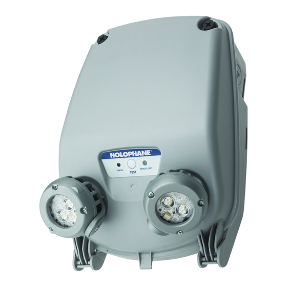
Acuity Brands 912-00031-002 Manual - Page 3
Browse online or download pdf Manual for Lighting Equipment Acuity Brands 912-00031-002. Acuity Brands 912-00031-002 20 pages. Emergency lighting unit

page 2
IMPORTANT: Provide each unit with a single-phase AC un-switched power supply from a 120 V to 347 V circuit used for normal lighting.
PRODUCT DAMAGE WILL OCCUR IF THE RATED INPUT VOLTAGE IS EXCEEDED.
WARNING: During installation of remotes, input wires from main unit to remote units must NOT be connected to each other or connected to
ground. Failure to due so will lead to failure of the main unit.
NOTE: The battery must be connected to the charger board prior to applying AC power to the unit. Battery damage may occur if the battery is
connected longer than 24 hours without continuous AC power provided. See also "Important Battery Information", page 3.
NOTE: The maximum mounting height of DSL3 SP640L is 31.9 feet, the DSL3 SP1100L is 47.2 feet and the DSL3 SP2200L is 64.5 feet
respectively, to meet the minimum illumination requirements of NFPA 101 (current Life Safety Code).
Before installation, choose a location that allows adequate clearance for sliding the Rear Housing onto the Mounting Bracket
NOTE:
(minimum 6-1/2" above top edge of Bracket)
NOTE: Do not connect battery or power unit until remote units (if applicable) are fully connected and wires are isolated from other
potentials (i.e. remote wires shall be isolated from earth ground).
MOUNTING BRACKET
Universal Mounting Bracket
1
Wall/Ceiling
Mounting
)
Holes (4
Mounting
Bayonets (4)
a. Wall/Ceiling mounting-
Install using four (4) 30 lbs. min. Pullout rated fasteners. Mounting surface should be suitable to support 120 lbs.
b. Pole/Column Mounting-
1.
Unistrut Mounting holes for most standard configurations.
2.
Steel Banding Slots for routing around poles and I-beams. (See "Pole Mount Banding slots "above).
After the Mounting Bracket is in place and the conduit is near, slide the enclosure downward onto the Mounting Bayonets
(See Figure 2). The enclosure will be in place when the snap-lock feature is engaged in the hole in the Mounting Bracket.
SURFACE CONDUIT MOUNTING
At the top left or either side of the housing, drill a hole sized
1
for the chosen conduit fitting. Conduit entry points can
accommodate a hole up to 1" diameter and have a wall
thickness up to .25". Secure mounting plate to wall surface
using fasteners with a minimum pullout rating of 30 lbs. each.
IMPORTANT: prior to drilling out a
hole on the top conduit location,
remove the charger board assembly
to ensure no damage occurs to the
charger board.
Three drill location
provided for conduit entry.
(One is opposite side)
INSTALLATION and MOUNTING
Rear housing snap lock
feature works in this
hole
Unistrut
Holes (4)
Locate mounting bracket in desired location using "Wall/Ceiling Mounting Holes" (see Fig. 1).
Mounting
®
Pole Mount Banding
Slots (8)
Remove any debris from the enclosure, as it may harm
2
electronic components or compromise the enclosure seal.
Install a
UL-listed, water-tight fitting
size of the incoming conduit and hole drilled in step 1. The
fitting must prevent water ingress at the sealing joint with the
enclosure, as well as from moisture which may be inside the
conduit itself. Make code-approved wire connections to the
AC power supply and remote lamps (if applicable). See Wiring
Diagram, page 6.
IMPORTANT:
recommendations when attaching
conduit to the conduit fitting. Failure to
do so can lead to moisture buildup in
the conduit which may leak into the
housing and damage the unit.
FLEXIBLE CONDUIT ONLY
2
which is suitable to the
Follow any manufacture
