Acuity Brands Lithonia Lighting KSF Installation Instructions - Page 2
Browse online or download pdf Installation Instructions for Lighting Equipment Acuity Brands Lithonia Lighting KSF. Acuity Brands Lithonia Lighting KSF 3 pages.
Installation Instructions
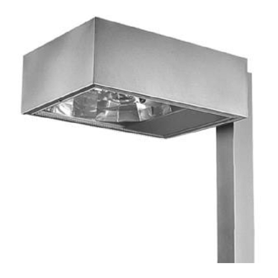
KSF
KSF
Arm mounted-Rectilinear
Full cutoff Lighting
DELIVERY: Upon receipt of fixture and accessories (packed separately), thoroughly inspect for any freight damage. All damage should be reported to the delivery
carrier. Compare the catalog description listed on the packing slip with the fixture label on the inside of the housing to be sure you have received the correct
merchandise.
1. POLE: (see Figure 1) Insert the mounting plate inside pole or tenon adapter, aligning the three (3) mounting holes in plate with the three (3) mounting holes provided on
pole. Slide threaded rods through top and bottom mounting holes in poles and start to thread the rods into the matching holes in the mounting plate. A few turns is all that
is needed. Place one of the enclosed gaskets over threaded rods and against pole.
WALL and WOOD:
CAUTION: APPLY A CONTINUOUS BEAD OF WEATHER - PROOF CAULKING BETWEEN MOUNTING PLATE AND WALL TO ENSURE WEATHER
- TIGHT INTEGRITY OF ELECTRICAL COMPONENTS. Wall or Wood Pole Mounting - Place mounting plate on mounting surface. For WB (see Figure 2), secure the mounting
plate to the wall with four (4) (minimum) 1/2" to (maximum) 5/8" fasteners (by others). For WW (see Figure 3): mark first and fifth holes of plate; remove mounting plate and drill
5/8" hole at marked locations (minimum of 3/4" to accept fixture mounting rods); secure mounting plate to mounting surface (fasteners not provided) using second and fourth
holes. Insert the two threaded fixture mounting rods into mounting plate and turn to secure.
2. The mounting arm is cut with a 2° angle on one end to pitch fixture slightly upward. In order to mount arm properly, follow the instructions on the label that is on the
arm. To mount arm, slide arm over threaded rod using the bolt guides inside arm. Again, check to see that label is in the correct place. Place remaining gasket over
threaded rods and against mounting arm.
threaded rods between the mounting arm gasket and the fixture housing (as shown in Figure 4).
3. To simplify installation, remove lens frame from fixture. To mount fixture, align the gasket to mounting holes between fixture housing and mounting bracket. Insert
threaded rods into fixture, being careful to align gasketing between fixture housing and mounting arm. Install split lockwashers and cap nuts (furnished) on threaded
rod and tighten securely. During this process, be sure the fixture is mounted straight on pole or wall.
4. Pull both supply and fixture leads into mounting arm or pole top. Complete the wiring through the hand-hole access cover or in the pole top following instruction listed
under wiring fixture. Lamp the fixture following lamping instructions and install lens frame. Swing hand-hole cover into closed position and secure (when applicable).
LAMP INSTALLATION AND RE-INSTALLATION: Verify the lamp is the correct source and wattage. Screw the lamp securely into the socket; back it out one or two
turns, then screw lamp back in, making sure it is secure and properly seats lamp in the socket. Lamp at end of life should be promptly replaced. Failure to do so may
cause damage to components.
OPTICAL ROTATION —
WARNING: Burn Risk - Ensure lamp cools before performing maintenance. Open door assembly. Remove lamp. Gently pull reflector away
from reflector skirt. Rotate optical assembly in 90 degree increments to desired light output as indicated by light distribution arrow on reflector. Insert reflector
assembly back into opening by lining up the four ball studs and their receptacles and gently pushing down until all four ball studs click into place (you will hear an
audible click). Reinstall lamp (see above). Close door assembly.
TB - Tapped Ballast - The tapped ballast will be wired for 277 volt at the factory. To wire a fixture that contains
a tapped ballast, first determine correct line voltage. Then select the proper fixture voltage lead, remove
crimped cap and connect to supply voltage lead. The fixture lead marked COM should then be connected
to the neutral supply lead on all multi-voltage, be sure to cap off all unused fixture leads individually.
TROUBLESHOOTING - If this fixture fails to operate properly, check to make sure: • The correct lamp is
properly installed.
•The fixture is wired correctly.
correctly. •The line voltage at the fixture is correct.
Tools Required: Straight blade screwdriver and 3/4" open-end wrench (for wall or wood pole: also need a drill with 5/8"
POLE MOUNTING
(figure 1)
NOTE:
KSF3 requires an additional external mounting plate and gasket (parts in fixture carton) to be placed onto the
•The lamp is not faulty.
Lithonia Lighting Outdoor
One Lithonia Way, Conyers, GA 30012
Phone: 800-279-8041 Fax: 770-918-1209
www.lithonia.com
WALL BRACKET (WB)
(figure 2)
Handhole
cover
• The fixture is grounded
Screw
2-required
WALL OR WOOD POLE MOUNTING (WW)
(figure 3)
Gasket
3-required
Mounting
label
(figure 4)
Gasket
Pole
mounting
arm
Threaded rod
2-required
KSF3 Exterior
Mounting Plate
(figure 4)
Part Number: RJ5210105 Rev C
Revision Date: 09-26-08
Page 1
bit).