Cisco IC3000 Hardware Installation Manual - Page 28
Browse online or download pdf Hardware Installation Manual for Gateway Cisco IC3000. Cisco IC3000 37 pages. Industrial compute gateway
Also for Cisco IC3000: Product Documentation (12 pages)

Connecting to DC Power
WARNING: In device installations in a hazardous location, the DC power source could be located away
from the vicinity of the device. Before performing any of the following procedures, locate the DC circuit to
ensure that the power is removed and cannot be turned on accidentally, or verify that the area is nonhazardous
before proceeding. Statement 1059
WARNING: Installation of the equipment must comply with local and national electrical codes. Statement
1074
WARNING: Explosion Hazard—Substitution of components may impair suitability for Class I, Division
2/Zone 2. Statement 1083
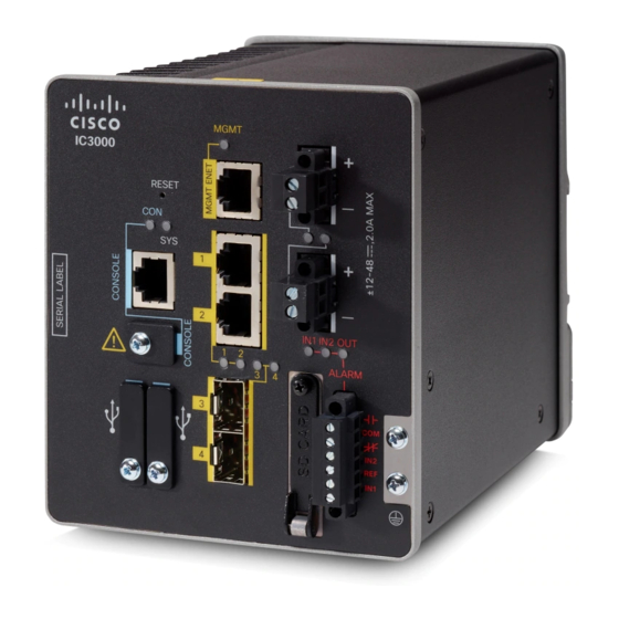
You connect DC power to the device through the front panel connectors. The device has a dual-feed DC power
supply; two connectors provide primary and secondary DC power (DC-A and DC-B).
Each power connector has an LED status indicator. The device power connectors are attached to the device
chassis. Each power connector has screw terminals for terminating the DC power. All connectors are attached
to the device front panel with the provided captive screws.
The power connector labeling is on the panel. The positive DC power connection is labeled "+", and the return
connection is labeled "–".
The device can operate with a single power source or with dual power sources. When both power sources are
operational, the device draws power from the DC source with the higher voltage. If one of the two power
sources fail, the other continues to power the device.
To connect DC power to your Cisco IC3000, follow these steps:
Step 1
Locate the two power connectors on the device front panel labeled DC-A and DC-B.
Figure 9: Power Connector
Step 2
Identify the connector positive and return DC power connections. The "+" is the Positive DC power connection, and the
"-" is the Return DC power connection.
Step 3
Measure two strands of twisted-pair copper wire long enough to connect the power converter to the DC power source.
For DC connections from the power converter to the DC source, use 18 to 20 AWG (2.6mm) twisted-pair copper wire.
Step 4
Using a 18-gauge (1.02mm) wire-stripping tool, strip the ground wire and both ends of the twisted pair wires to 0.25 inch
(6.3 mm) ± 0.02 inch (0.5 mm). See
strip more than 0.27 inch (6.8 mm) of insulation from the wires. Stripping more than the recommended amount of wire
can leave exposed wire from the power and relay connector after installation.
Cisco IC3000 Industrial Compute Gateway Hardware Installation Guide
26
Figure 10: Stripping the Power Connection Wire, on page
Connecting the Cisco IC3000
27, number 1. Do not
