Crowcon 40/40R Operating And Maintenance Instructions Manual - Page 7
Browse online or download pdf Operating And Maintenance Instructions Manual for Gas Detectors Crowcon 40/40R. Crowcon 40/40R 20 pages. Infra-red sf6 and refrigerant gas detector
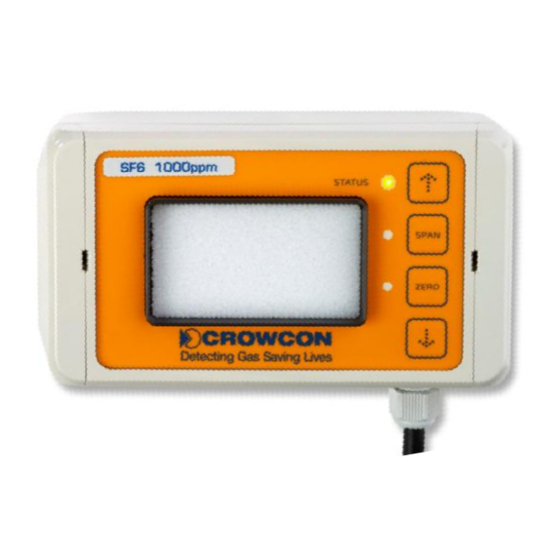
Mount device vertically to the wall using the 4 screw holes (fig. 7) with the cable gland
pointing downwards.
Mounting hole spacing: 127.5mm x 62.5mm. Mounting hole diameter: 4mm.
Warning: never install the detector with the front panel facing upwards. Doing so may
lead to the IR sensor filter becoming blocked by dust/contaminants which could
prevent gas from reaching the sensor.
2.3.
Compensation of the ambient pressure
In order for the transmitter to be as flexible as possible and to facilitate the use both at sea
level and in higher regions, the so-called real gas formula must be taken into account. As a
result of the physical properties of gases, the density will change, depending on the relevant
altitude and, due to this fact; the absorption of the IR radiation inside the measuring cell will
change accordingly. Without any pressure compensation, it would lead to inaccuracies in the
measurement of the concentration and possibly to faulty data.
As the ambient pressure must be taken into account when measuring the concentration in
diffusion mode, a pressure sensor is already integrated firmly in the transmitter.
For this reason no setting or parameterization by the user is required.
3. Start-up
3.1.
Wiring instructions
Electrical connections are made via the connector ST1 - see Figure 2.
In order to avoid any errors and damage, the system must be mounted while the power has
been switched off. It is imperative that the following order is observed:
1. Switch off the power.
2. Mount the transmitter in the desired position. While doing this, adequate distance to
live parts must remain in order to avoid short circuits and damage.
3. The installation in the vicinity of ventilators, windows, ventilation shafts and similar
facilities must be avoided. Any air flow or drought near the transmitter may lead to
inaccurate readings and false alarms or inadequate function.
F-Gas Detector Instructions
Figure 7: mounting
holes