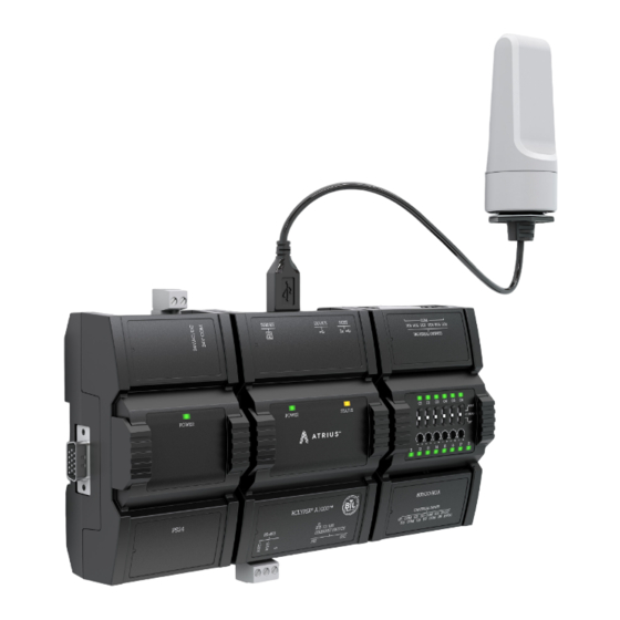
Acuity Controls ATRIUS ECYA1000 Installation Manual - Page 8
Browse online or download pdf Installation Manual for Relays Acuity Controls ATRIUS ECYA1000. Acuity Controls ATRIUS ECYA1000 14 pages.

4-0 DIP Switch and Jumper
Identification and Configuration
4-4 Output Wiring
Output options must be properly configured in EC-gfxProgram to ensure correct output values. The table below shows the 8UI6UOHOA modules' output
designation for each IO type. For terminal block connector wiring best practices, see General Wiring Recommendations. Outputs can be connected as
follows.
Before connecting a sensor to the controller, refer to the installation guide of the equipment manufacturer.
•
For a wire length less than 75' (23m), either a shielded or unshielded 18AWG wire may be used.
•
For a wire up to 200' (61m) long, a shielded 18AWG wire is recommended.
•
The shield of the wire should be grounded on the controller side only and the shield length should be kept as short as possible.
Sensor Input Type
•
Discrete 0 or 12VDC digital, Pulse, or PWM output controlling
a 12VDC relay.
•
0 to 20mA current output – set the DIP switch to 0-20mA.
•
See DIP Switch and Jumper Identification and Configuration
on page 5 for more information about how to set the DIP
Switch.
•
0 to 10VDC voltage output.
•
0 to 10VDC voltage output controlling an analog actuator that
is powered by an external 24VAC power source.
Acuity Brands | One Lithonia Way Conyers, GA 30012 Phone: 800.535.2465 www.acuitybrands.com © 2019 Acuity Brands Lighting, Inc. All rights reserved. Rev. 11/07/2019
- cont'd
8UI6UOHOA
Modules' Input
Designation
•
UOx
•
UOx
•
UOx
•
UOx
Input Connection Diagram
8 of 14
