Motorola CDM1250 Service & Installation Manual - Page 9
Browse online or download pdf Service & Installation Manual for Two-Way Radio Motorola CDM1250. Motorola CDM1250 32 pages. Cdm-series control station
Also for Motorola CDM1250: User Manual (50 pages)
Overview
This section introduces you to the CDM Control Station; out-
lines major components; physical appearance; accessories;
general information about cables, and basic assembly of the
Control Station.
CDM Control Station
The Control Station provides a low cost integrated base sta-
tion package with enhanced control and audio accessory fea-
tures. The station is unique because it is designed to use off-
the-shelf mobile radios for the transceiver. This design pro-
vides the additional benefits of quick repair and minimizing
inventory. The unit is completely self-contained, with radio,
power supply and necessary electronics mounted in an
attractive desktop cabinet.
A few features that distinguish the Control Station:
• Portability
The Control Station is a self-contained, portable,
desktop unit.
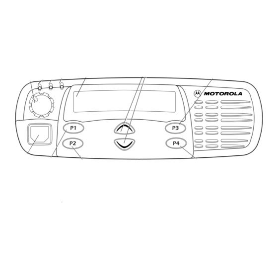
• Local Desktop Control
The Control Station provides enhanced control func-
tions through conveniently located front panel but-
tons. These functions include: Intercom, Supervisor,
Monitor, and Transmit. The front panel also houses
an internal microphone to allow communication
without the aid of an external audio accessory.
• Audio Accessory Connections
The Control Station provides easily accessible audio
ports from the front panel that allow direct connec-
tion of a headset or desk microphone.
• External Accessories
The Control Station provides a 16-pin accessory con-
nector for additional peripheral components
• Fan
The Control Station has a single speed , thermal switch
controlled fan.
• Power Supply
The Control Station has a 15 Ampere, continuous
duty switch mode power supply.
Mobile Radio Compatibility
The CDM Control Station was designed to incorporate the
CDM750, CDM1250, or CDM1550 mobile radios.
October, 2004
CDM Control Station
Physical Description
The following paragraphs describe the physical characteris-
tics of the Control Station.
• CDM Control Station Housing
• CDM Control Station Fan Assembly
• CDM Control Station Power Supply
• CDM Control Station Interface Circuit Boards
CDM Control Station Housing
The Control Station housing provides the necessary mobile
mounting that will make up the customer's free-standing
Control Station. The Control Station is shipped from the fac-
tory with the fan assembly, control interface, and power sup-
ply already installed in the housing. Before you can assemble
the Control Station, the housing must be partially disassem-
bled as described in Section 3, CDM Control Station Instal-
lation of, this manual.
CDM Control Station Fan Assembly
The fixed-speed 12 VDC fan assembly is mounted onto the
rear wall of the Control Station cabinet. A thermal switch
from the power supply is connected to the heatsink on the
underside of the transmit radio and monitors the temperature
of the radio. The fan turns on when necessary.
CDM Control Station Power Supply
The Control Station operates using voltages generated by the
HPN9033 power supply. The power supply operates from a
115 / 230 VAC (switch selectable) power source. The power
supply provides power for the fan assembly and radio. The
power to the interface electronics is obtained from the radio's
accessory connector. The power supply has three connectors:
• One pigtail with a 2-prong "Ford" connector to mate
with the radio power connector.
• One pigtail with a 6-position connector to power the
fan.
• One IEC ac receptacle for various line cords (U.S.
Standard, 3-prong, 115 VAC cord provided).
A slide switch on the power supply allows thermal control or
continuous ON fan operation.
6880309N15-A
Section 1
Introduction to the
1-1