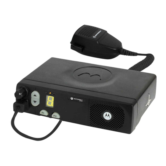
Motorola CM140 Service Information - Page 12
Browse online or download pdf Service Information for Two-Way Radio Motorola CM140. Motorola CM140 26 pages. Commercial series controlhead
Also for Motorola CM140: User Manual (5 pages)

2-6
The HOOK line (J102-6) is used to inform the uP which type of microphone or SCI lead is connected
to the microphone socket. The voltage of the HOOK line is monitored by the uP (port PE0,
MIC_SENSE) through a resistor divider on the main board. When the HOOK line is grounded (on
hook condition) or floating (2.8V nominal), the uP sets the mux (U8) for keypad operation to allow the
use of microphones with a keypad. When the HOOK line is connected to 9.3V, the uP sets the mux
for SCI operation. This mode is also used to select low cost mic operation where the gain of the
microphone path is increased (on the main board) to compensate for not having a pre-amp in the low
cost mic.
If the BOOT_RES (J102-7) line is connected to >5V (e.g. 9.3V) at turn-on then the uP will start in
boot mode instead of normal operation. This mode is used to programme new firmware into the
FLASH memory (U404 mainboard).
3.7
Speaker
The controlhead contains a speaker for the receiver audio. The receiver audio signal from the
differential audio output of the audio amplifier located on the radio's controller is fed via connector
J103-1, 2 to the speaker connector P101 pin 1 and pin 2. The speaker is connected to the speaker
connector P101. The controlhead speaker can be disconnected if an external speaker, connected on
the accessory connector, is used.
3.8
Electrostatic Transient Protection
Electrostatic transient protection is provided for the sensitive components in the controlhead by
diodes VR1 - VR4. The diodes limit any transient voltages to tolerable levels. The associated
capacitors provide Radio Frequency Interference (RFI) protection.
THEORY OF OPERATION
