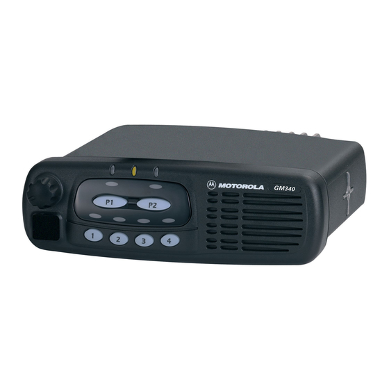
Motorola GM160 Service Information - Page 29
Browse online or download pdf Service Information for Two-Way Radio Motorola GM160. Motorola GM160 34 pages. Professional radio
Also for Motorola GM160: User Manual (44 pages), Basic Service Manual (46 pages), Service Information (32 pages), Service Information (32 pages), User Manual (44 pages)

Troubleshooting Flow Chart for 45W Transmitter (Sheet 1 of 2)
Troubleshooting Flow Chart for Transmitter (Sheet 2 of 2)
3.1
No or too low Power when keyed
Check Voltage at Pin 2 & 3 of U3401
Replace
Q3421
Check Components
between ASFIC and
Q3431 before re-
placing Q3431
Check Components
between Q3431 &
Q3441
Check PA Stages
Pin 2
YES
Voltage 0.62
* Voltage at
Pin 1?
NO
Replace U3401
YES PCIC U3501
Pin 24 2-4V
DC?
NO
Check Bias Tuning be-
fore replacing
PCIC U3501
YES
ASFIC
U0221 Pin 6
1-4V DC?
NO
Check Bias Tuning be-
fore replacing
ASFIC U0221
NO
RF Voltage
Q3441 Base
>5V?
YES
Check Components
between Q3441 & An-
tenna Connector
Pin 3
NO
Voltage 0.51
* Voltage at
Pin 1?
YES
Supply
0V
Voltage
Bias 1 DC
Voltage at
TP3406?
2-4V
Supply
Voltage
0V
Bias 2 DC
Voltage at
TP3407?
1-4V
NO
RF Voltage
at TP3401
>100mV?
YES
NO
RF Voltage
U3401 Pin 6
>3V?
YES
NO
RF Voltage
Q3421 Gate
>1V?
YES
YES RF Voltage
NO
Q3431 Gate
>4V?
Replace U3401
Replace Q3421
Replace Q3431
Check FGU (U3301)
Check Components
between TP3401 &
C3417
Check Components
between C3417 &
Q3421
Check Components
between Q3421 &
Q3431
3-7
