Motorola APX Mobile Instruction Manual - Page 36
Browse online or download pdf Instruction Manual for Radio Motorola APX Mobile. Motorola APX Mobile 46 pages. Dual-radio o7 control head system

5-2
5.2
Trunk Units
This section describes trunk unit installations.
5.2.1
Radio Mounting
The APX Dual-Radio System uses CAN bus to connect two radios and the O7 Control Head
together. The Primary Radio connects directly to the Secondary Radio, and the Primary Radio
connects directly to the control head. It is recommended that the control head connect to the Primary
radio. There are two mounting styles which are "Stack Mounting" and "Side-By-Side Mounting".
The Stack Mounting is only available for MP-MP combination, when both radios are Mid-Power
models.
For the APX Mobile Radio Mounting, refer to (Section 2.2, Radio Mounting) of the APX Mobiles And
Control Heads Installation Manual (P/N 6878215A01).
5.2.1.1 Side-By-Side Installation
Figure 5-1
and
both Mid-Power and High-Power radios. Following are the installation procedures:
• Use the Standard Trunnion (P/N HLN7002_), for installing each radio.
• Mount the Primary and Secondary Radios on the Trunnions.
NOTE: Mark the Primary and Secondary Radios with the included P and S labels
(P/N 54009321002). Marking the radios allows for proper setup.
• Connect the Accessory Connector (P/N HLN6863_) to both radios.
• Connect the DC Power Cables (P/N HKN4192_) to each radio. Connect the other end of the
cables to the battery terminals (RED POSTITIVE).
• Install the O7 Control Head, refer to the APX Mobiles And Control Heads Installation Manual
(P/N 6878215A01).
• Install two speakers (P/N HSN4031_).
• Connect the Primary speaker to the on-line connector on the control head power cable.
Connect the Secondary speaker to the accessory connector on the Secondary Radio
transceiver. Use the Speaker Extension Cable (P/N HKN6246_), if additional length is needed.
• Install the antennas as per instructions provided with each antenna, refer to the APX Mobiles
And Control Heads Installation Manual (P/N 6878215A01).
• Connect the Control Head CAN Cable between the Primary Radio and the O7 Control Head.
• Connect the short CAN Cable (P/N HKN6245_), between both radios.
• Connect the Palm Microphone (P/N HMN1090_), to the front of O7 Control Head.
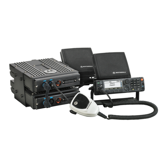
5.2.1.2 Stack Mount Installation
Figure 5-3
shows a complete setup of APX Mid-Power Dual-Radio Stack Mount Installation.
Following are the installation procedures:
• Use the special Dual Trunnion (P/N HLN7045_), for installing two radios. Tighten the screws to
verify the Trunnion sides are flush with the radios. Once flush, torque the screws to 50 in-lbs.
NOTE: Mark the Primary and Secondary Radios with the included P and S labels
(P/N 54009321002). Marking the radios allows for proper setup.
• Connect the Accessory Connector (P/N HLN6863_), to the radios.
July 30, 2014
Figure 5-2
show a complete setup of APX Dual-Radio Side-By-Side Installation, for
APX Dual-Radio Installation: Trunk Units
MN000770A01-AA
